

Today we will study PAT (Port Address Translation), a technology for translating IP addresses using ports, and NAT (Network Address Translation), a technology for converting IP addresses of transit packets. PAT is a specific case of NAT. We will cover three topics:
— private, or internal (intranet, local) IP addresses and public, or external IP addresses;
— NAT and PAT;
— configuring NAT/PAT.
Let's start with Private IP addresses. We know they are divided into three classes: A, B, and C.
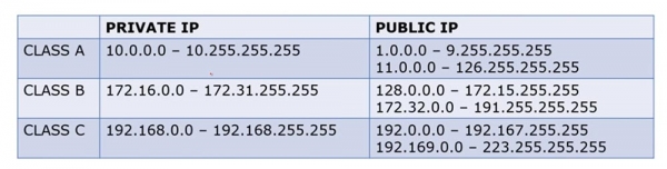
Internal addresses of Class A occupy the range of 'tens' from 10.0.0.0 to 10.255.255.255, while external ones occupy the range from 1.0.0.0 to 9.255.255.255 and from 11.0.0.0 to 126.255.255.255.
Internal addresses of Class B occupy the range from 172.16.0.0 to 172.31.255.255, while external ones range from 128.0.0.0 to 172.15.255.255 and from 172.32.0.0 to 191.255.255.255.
Internal addresses of Class C occupy the range from 192.168.0.0 to 192.168.255.255, while external ones are from 192.0.0.0 to 192.167.255.255 and from 192.169.0.0 to 223.255.255.255.
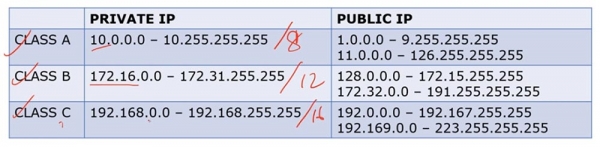
Class A addresses are /8, Class B addresses are /12, and Class C addresses are /16. Thus, external and internal IP addresses of different classes occupy different ranges.
We have discussed the difference between private and public IP addresses multiple times. In general, if we have a router and a group of internal IP addresses, when they attempt to access the internet, the router converts them to external IP addresses. Internal addresses are used exclusively in local networks, not on the Internet.
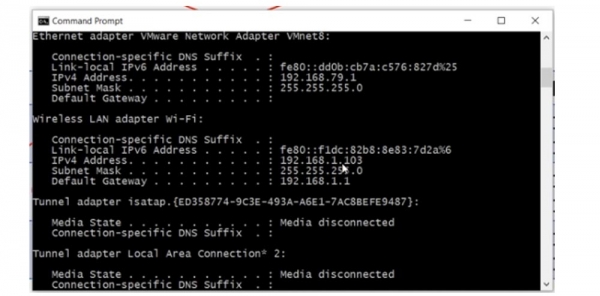
If I check my computer's network parameters using the command line, I will see my internal LAN IP address 192.168.1.103.
To find out my public IP address, I can use an internet service like 'What is my IP?'. As you can see, the external address of the computer 78.100.196.163 differs from its internal address.
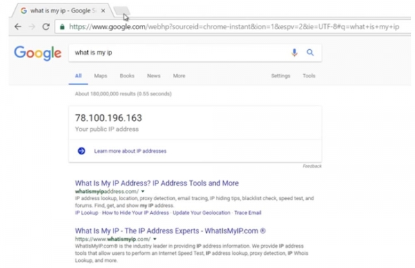
In all cases, my computer is visible on the internet by its external IP address. So, the internal address of my computer is 192.168.1.103, and the external one is 78.100.196.163. The internal address is used only for local communication; it cannot access the internet. For that, you need a public IP address. You might recall why the division into private and public addresses was made by reviewing the video tutorial Day 3.
Let's consider what NAT is. There are three types of NAT: static, dynamic, and 'overloaded' NAT, or PAT.
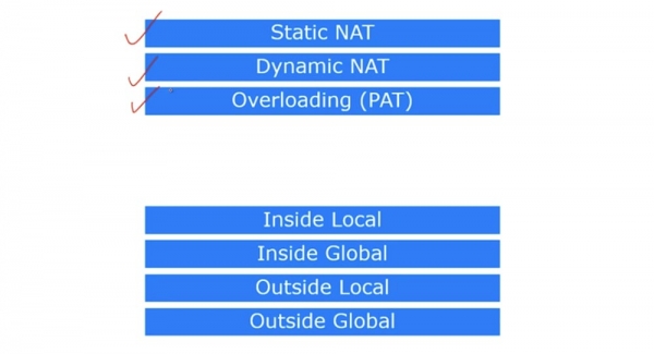
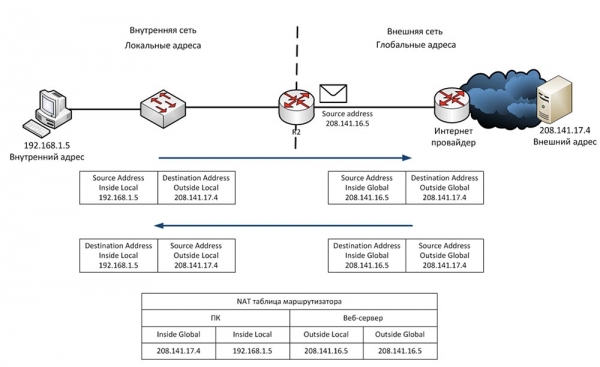
Cisco defines four terms describing NAT. As mentioned, NAT is a mechanism that converts internal addresses to external ones. If a device connected to the internet receives a packet from another device in the local network, it simply drops that packet since the format of the internal address doesn’t match the format of addresses used in the global internet. Therefore, the device must obtain a public IP address to access the internet.
The first term is Inside Local, which refers to the IP address of a host in the internal, local network. Simply put, it's the primary source address like 192.168.1.10. The second term, Inside Global, is the IP address of the local host as seen in the external network. In our case, this is the external port IP address of the router, 200.124.22.10.
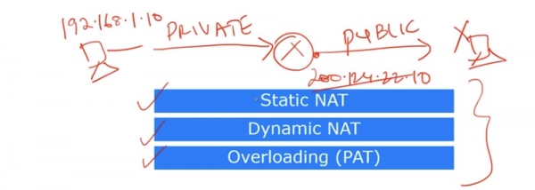
It can be said that Inside Local is a private IP address, while Inside Global is a public IP address. Remember that the term Inside refers to the source of the traffic, whereas Outside pertains to the destination of the traffic. Outside Local is the IP address of a host in the external network as seen by the internal network. In simpler terms, it’s the recipient's address visible from the internal network. An example of such an address is the IP address 200.124.22.100 of a device located on the internet.

Outside Global is the IP address of a host visible in the external network. In most cases, the Outside Local and Outside Global addresses appear the same, because even after the conversion, the destination IP address remains visible to the source as it was before the conversion.
Let’s consider what static NAT represents. Static NAT refers to a one-to-one conversion of internal IP addresses to external ones, or 'one-to-one' mapping. When devices send traffic to the internet, their Inside Local addresses are converted to Inside Global addresses.
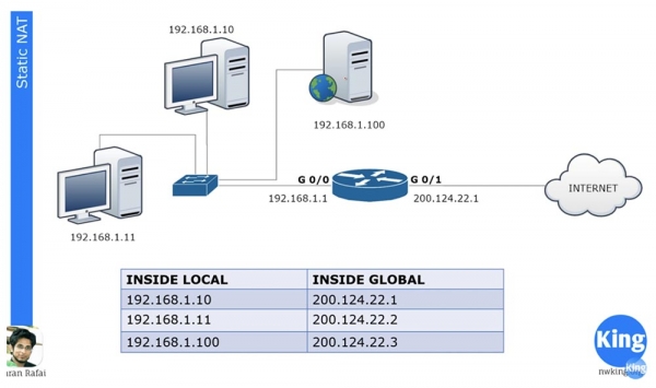
In our local network, there are three devices, and when they are about to access the internet, each one obtains its own Inside Global address. These addresses are statically assigned to the traffic sources. The 'one-to-one' principle means that if there are 100 devices in the local network, they receive 100 external addresses.
NAT was created to save the Internet from running out of public IP addresses. Thanks to NAT, many companies and networks can share a common external IP address, to which local device addresses are converted when accessing the Internet. You could argue that in this case, there is no saving of address space with static NAT since a hundred local computers are assigned a hundred external addresses, and you would be absolutely correct. However, static NAT still has a number of advantages.
For example, we have a server with an internal IP address of 192.168.1.100. If a device from the Internet wants to communicate with it, it cannot use the internal destination address; it must use the server's external address of 200.124.22.3. If static NAT is configured on the router, all traffic directed to 200.124.22.3 is automatically redirected to 192.168.1.100. This ensures external access to local network devices, in this case, to the company's web server, which may be necessary in certain situations.
Let's consider dynamic NAT. It is very similar to static NAT but does not assign permanent external addresses to each local device. For instance, we have 3 local devices and only 2 external addresses. If the second device wants to access the Internet, it will be assigned the first available IP address. If after it a web server wants to access the Internet, the router will assign it the second available external address. If after that the first device wants to go to the external network, there will be no available IP address for it, and the router will drop its packet.
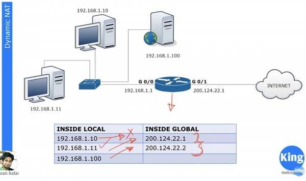
We may have a hundred devices with internal IP addresses, and each of these devices can access the Internet. But since we do not have static external address assignments, no more than 2 devices out of a hundred can go online simultaneously, because we only have two dynamically assignable external addresses.
Cisco devices have a fixed address translation time, which by default is set to 24 hours. This can be changed to 1, 2, 3, or 10 minutes, or any other desired time. After this period, external addresses are released and automatically returned to the address pool. If at that moment the first device wants to access the internet and an external address is available, it will receive that address. The router contains a NAT table that updates dynamically, and as long as the translation time has not expired, the assigned address remains with the device. In simpler terms, dynamic NAT operates on the principle of 'first come, first served.'
Let’s consider what overloaded NAT, or PAT, entails. This is the most common type of NAT. In your home network, there may be many devices – a PC, smartphone, laptop, tablet, and they all connect to a router that has one external IP address. PAT allows multiple devices with internal IP addresses to access the internet simultaneously under a single external IP address. This is made possible because each private internal IP address uses a specific port number during the communication session.
Suppose we have a single public address 200.124.22.1 and numerous local devices. When they access the internet, all these hosts will receive the same address 200.124.22.1. The only difference that will distinguish them from each other is the port number.
If you recall the discussion on the transport layer, you know that the transport layer contains port numbers, and the source port number is a random number.
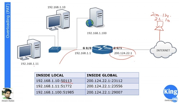
Assume there is a host in the external network with the IP address 200.124.22.10, which is connected to the internet. If the computer 192.168.1.11 wants to communicate with the computer 200.124.22.10, it will create a random source port 51772. Meanwhile, the destination port of the external network computer will be 80.
When the router receives a packet from the local computer directed towards the external network, it translates its local address Inside Local to the Inside Global address 200.124.22.1 and assigns port number 23556. The packet will reach the computer 200.124.22.10, which must then send back a response according to the handshake procedure, with the destination being address 200.124.22.1 and port 23556.
The router has a NAT translation table, so when it receives a packet from an external computer, it will identify the Inside Local address that corresponds to the Inside Global address as 192.168.1.11:51772 and will forward the packet to it. After this, the connection between the two computers can be considered established.
At the same time, you could have a hundred devices using the same address 200.124.22.1 for communication, but with different port numbers, allowing them all to simultaneously connect to the internet. This is why PAT is such a popular method of translation.
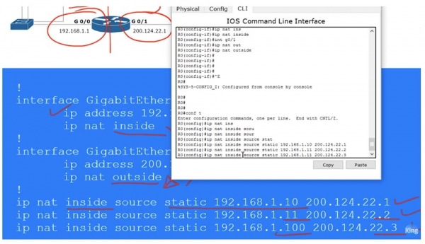
Let's look at the configuration of static NAT. For any network, it is first necessary to define the incoming and outgoing interfaces. The diagram shows a router that passes traffic from port G0/0 to port G0/1, meaning from the internal network to the external network. Thus, we have an incoming interface 192.168.1.1 and an outgoing interface 200.124.22.1.
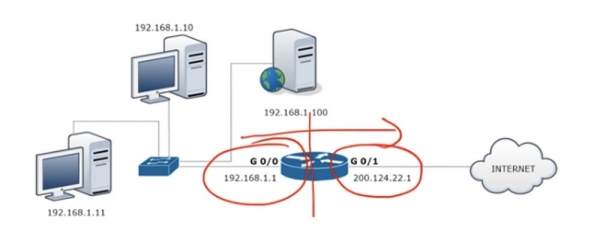
To configure NAT, we go to the interface G0/0 and set the parameters ip address 192.168.1.1 255.255.255.0 and specify that this interface is the incoming one using the command ip nat inside.
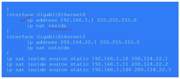
Similarly, we configure NAT on the outgoing interface G0/1, specifying ip address 200.124.22.1, the subnet mask 255.255.255.0, and ip nat outside. Remember that dynamic NAT translation always occurs from the incoming to the outgoing interface, from inside to outside. Naturally, for dynamic NAT, the response comes to the incoming interface through the outgoing one, but during traffic initiation, the in-out direction is activated. In the case of static NAT, traffic initiation can occur in either direction— in-out or out-in.
Next, we need to create a static NAT table, where each local address corresponds to a separate global address. In our case, there are 3 devices, so the table will consist of 3 entries that indicate the Inside Local IP address of the source being transformed into the Inside Global address: ip nat inside static 192.168.1.10 200.124.22.1.
Thus, in static NAT, you manually specify the translation for each local host address. Now I will switch to Packet Tracer and perform the settings described above.
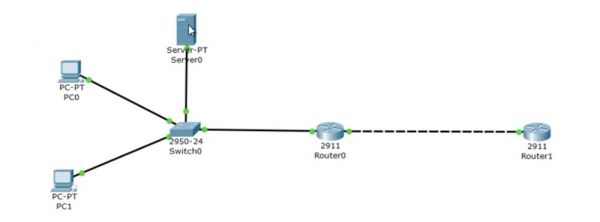
At the top, we have server 192.168.1.100, below it is computer 192.168.1.10, and at the very bottom is computer 192.168.1.11. The port G0/0 of router Router0 has the IP address 192.168.1.1, while port G0/1 has 200.124.22.1. In the 'cloud' representing the internet, I placed Router1, which has been assigned the IP address 200.124.22.10.
I access the settings of Router1 and type the command debug ip icmp. Now, as soon as the ping reaches this device, a debug message will appear in the settings window, indicating what kind of packet it is.
Let's proceed to configure router Router0. I enter global configuration mode and call up interface G0/0. Next, I enter the command ip nat inside, then proceed to interface g0/1 and enter the command ip nat outside. This way, I assigned the router's inbound and outbound interfaces. Now I need to manually configure the IP addresses, that is, transfer the rows from the previously mentioned table into the settings:
Ip nat inside source static 192.168.1.10 200.124.22.1
Ip nat inside source static 192.168.1.11 200.124.22.2
Ip nat inside source static 192.168.1.100 200.124.22.3
Now I will ping Router1 from each of our devices and see which IP addresses the received ping will show. To do this, I place the open CLI window of router R1 on the right side of the screen to see the debug messages. Now I go to the command line terminal of PC0 and ping the address 200.124.22.10. After this, a message appears in the window, indicating that the ping was received from the IP address 200.124.22.1. This means that the local computer's IP address 192.168.1.10 was converted to the global address 200.124.22.1.
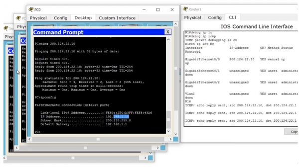
I do the same with the next local computer and see that its address was converted to 200.124.22.2. Then I send a ping from the server and see the address 200.124.22.3.
Thus, when traffic from a local network device reaches the router configured with static NAT, the router converts the local IP address to a global one according to the table and sends the traffic to the external network. To check the NAT table, I type the command show ip nat translations.
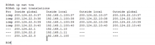
Now we can view all the translations that the router performs. The first column Inside Global shows the device's address before translation, which is the address under which the device is visible from the external network. Next is the Inside Local address, which is the address of the device in the local network. The third column shows Outside Local, while the fourth displays the Outside Global address; both of these addresses are the same because we do not alter the destination IP address. As you can see, after a few seconds, the table cleared because Packet Tracer has a short ping timeout.
I can ping the server at address 200.124.22.3 from router R1, and if we go back to the router settings, we can see that the table has filled up again with four ping rows, showing the translated destination address 192.168.1.100.
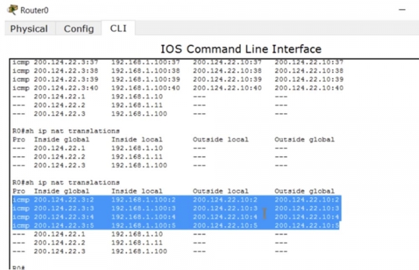
As I mentioned, even if the translation timeout occurs, when traffic is initiated from an external source, the NAT mechanism is automatically activated. This happens only when using static NAT.
Now let's look at how dynamic NAT works. In our example, we have 2 public addresses for three local network devices, but there can be dozens or even hundreds of such private hosts. At the same time, only 2 devices can access the internet. Let's examine how static and dynamic NAT differ beyond this.
As in the previous case, we first need to identify the router's incoming and outgoing interfaces. Next, we create a sort of access list, but this is not the ACL we discussed in the previous lesson. This access list is used to identify the traffic we want to translate. Here appears a new term: 'interesting traffic.' This is the traffic that interests you for some reason, and when this traffic matches the conditions of the access list, it falls under NAT and is translated. This term applies to traffic in many cases; for example, in the case of a VPN, the 'interesting' traffic is the traffic meant to be passed through the VPN tunnel.
We need to create an ACL that identifies interesting traffic; in our case, this is the entire network traffic 192.168.1.0, along with the corresponding reverse mask 0.0.0.255.
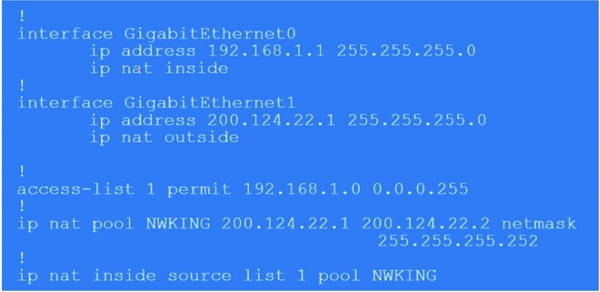
Next, we need to create a NAT pool using the command ip nat pool and specify the IP address pool 200.124.22.1 200.124.22.2. This means that we provide only two external IP addresses. Furthermore, the command uses the keyword netmask and enters the subnet mask 255.255.255.252. The last octet of the mask is (255 - the number of pool addresses - 1), so if you have 254 addresses in the pool, the subnet mask would be 255.255.255.0. This is a very important parameter, so when configuring dynamic NAT, ensure that you enter the correct value for netmask.
Next, we use the command that activates the NAT mechanism: ip nat inside source list 1 pool NWKING, where NWKING is the name of the pool and list 1 refers to access list ACL number 1. Remember — for this command to work, you must first create a pool of dynamic addresses and an access list.
So, under our conditions, the first device wishing to access the internet will be able to do so, the second device will also be able to, but the third will have to wait until one of the pool's addresses becomes available. Configuring dynamic NAT consists of four steps: defining the inbound and outbound interfaces, determining 'interesting' traffic, creating the NAT pool, and the actual configuration.
Now we will switch to Packet Tracer and attempt to configure dynamic NAT. First, we need to remove the static NAT settings by sequentially entering the commands:
no Ip nat inside source static 192.168.1.10 200.124.22.1
no Ip nat inside source static 192.168.1.11 200.124.22.2
no Ip nat inside source static 192.168.1.100 200.124.22.3.
Next, I create access list List 1 for the entire network with the command access-list 1 permit 192.168.1.0 0.0.0.255 and form the NAT pool using the command ip nat pool NWKING 200.124.22.1 200.124.22.2 netmask 255.255.255.252. In this command, I specified the name of the pool, the addresses included in it, and the subnet mask.
Then I specify what type of NAT it is – inside or outside, and the source from which NAT should gather information, in our case it's the list, using the command ip nat inside source list 1. After that, the system will prompt whether a whole pool or a specific interface is needed. I choose pool because we have more than one external address. If you select interface, you will need to specify the port with a specific IP address. The final command will look like this: ip nat inside source list 1 pool NWKING. Currently, this pool consists of two addresses 200.124.22.1 200.124.22.2, but you can freely change them or add new addresses that are not tied to a specific interface.
You must ensure that your routing table has updated so that any of these IP addresses in the pool point to this device; otherwise, you will not receive return traffic. To verify the settings are working, we will repeat the procedure of pinging the cloud router that we did for static NAT. I will open the Router 1 window to see the debug mode messages and ping it from each of the 3 devices.
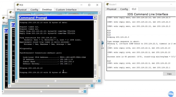
We see that all source addresses from where the ping packets come match the settings. At the same time, the ping from the PC0 computer does not go through because it ran out of a free external address. If you look at the settings of Router 1, you will see that currently, the pool addresses 200.124.22.1 and 200.124.22.2 are in use. Now I will disable the translation, and you will see how the lines disappear one by one. I restart the ping from PC0, and as you can see, now everything works because it was able to acquire the freed up external address 200.124.22.1.
How can you clear the NAT table and revert the specified address translation? Go to the settings of Router0 and type the command clear ip nat translation * with an asterisk at the end of the line. If you check the translation status now with the command show ip nat translation, the system will return an empty line.
To view NAT statistics, the command show ip nat statistics is used.
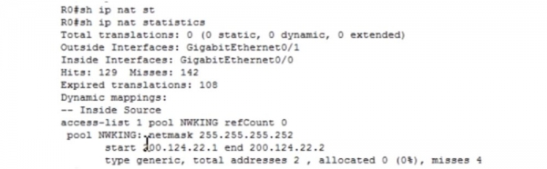
This is a very useful command that allows you to view the total number of dynamic, static, and extended NAT/PAT translations. You see that it equals 0 because we cleared the translation data with the previous command. Here, the incoming and outgoing interfaces are displayed, along with the number of successful and unsuccessful translation hits and misses (the number of misses is related to the lack of available external addresses for the internal host), the access list name, and the pool.
Now we will move on to the most popular type of IP address conversion – extended NAT, or PAT. To configure PAT, you need to go through the same steps as for dynamic NAT: identify the incoming and outgoing interfaces of the router, identify the 'interesting' traffic, create a NAT pool, and configure PAT. We can create the same pool from multiple addresses as in the previous case, but this is not necessary because in PAT the same external address is always used. The difference between setting up dynamic NAT and PAT lies solely in the keyword overload, which concludes the last configuration command. Once this word is entered, dynamic NAT automatically turns into PAT.
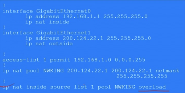
Additionally, you are using only one address in the NWKING pool, for example, 200.124.22.1, but specifying it twice as the starting and ending external address with a subnet mask of 255.255.255.0. You can simplify this by using the source interface parameter and the fixed address 200.124.22.1 of interface G0/1 instead of the line ip nat 1 pool NWKING 200.124.22.1 200.124.22.1 netmask 255.255.255.0. In this case, all local addresses when accessing the internet will be translated to this IP address.
You can also use any other IP address in the pool, not necessarily corresponding to a specific physical interface. However, in this case, you must ensure that all routers in the network can route the return traffic to the device you have chosen. The downside of NAT is that it cannot be used for end-to-end addressing because by the time the return packet gets back to the local device, its dynamic NAT IP address may have changed. In other words, you need to be sure that the selected IP address will remain available for the duration of the session.
Let's take a look at this through Packet Tracer. First, I need to remove the dynamic NAT with the command no Ip nat inside source list 1 NWKING and delete the NAT pool using the command no Ip nat pool NWKING 200.124.22.1 200.124.22.2 netmask 255.255.255.252.
Then I need to create a PAT pool using the command Ip nat pool NWKING 200.124.22.2 200.124.22.2 netmask 255.255.255.255. This time I am using an IP address that does not belong to a physical device because the physical device has the address 200.124.22.1, and I want to use 200.124.22.2. In our case, this works because we have a local network.
Next, I configure PAT with the command Ip nat inside source list 1 pool NWKING overload. After entering this command, we enable PAT address translation. To check the configuration's correctness, I go to our devices, the server, and two computers, and I ping from PC0 to Router1 at the address 200.124.22.10. In the router's settings window, I see debug lines showing that the source of the ping, as we expected, is the IP address 200.124.22.2. The ping sent from PC1 and the server Server0 also comes from this address.
Let's see what happens in the translation table of router Router0. You can see that all translations are successful; each device is assigned its own port, and all local addresses are linked to Router1 through the pool IP address 200.124.22.2.
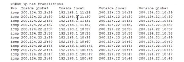
I use the command show ip nat statistics to view the PAT statistics.
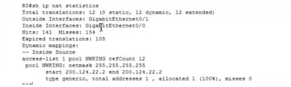
We see that the total number of translations, or address translations, is 12, and we can see the characteristics of the pool and other information.
Now I will do one more thing — I will enter the command Ip nat inside source list 1 interface gigabit Ethernet g0/1 overload. If after this I ping the router from PC0, it shows that the packet came from the address 200.124.22.1, that is, from the physical interface! This is an easier way: if you do not want to create a pool, which often happens when using home routers, you can use the IP address of the physical interface of the router as an external NAT address. This is how the address of your private host is most often translated for the public network.
Today we explored a very important topic, so you need to practice it. Use Packet Tracer to test your theoretical knowledge in solving practical tasks related to NAT and PAT configuration. We have reached the end of the ICND1 topic — the first exam of the CCNA course, so I will likely dedicate the next video lesson to summarizing.

Thank you for staying with us. Do you enjoy our articles? Would you like to see more interesting materials? Support us by placing an order or recommending us to your friends. 30% discount for Habr users on a unique entry-level server designed by us for you: (options available with RAID1 and RAID10, up to 24 cores and up to 40GB DDR4).
Dell R730xd for half the price? Only with us in the Netherlands! Dell R420 — 2x E5-2430 2.2GHz 6C 128GB DDR3 2x960GB SSD 1Gbps 100TB — from $99! Read about how
Source: habr.com
