

We have already covered local VLAN networks in the video lessons of Days 11, 12, and 13, and today we will continue our study in accordance with the ICND2 theme. I recorded the previous video, marking the end of the preparation for the ICND1 exam, a few months ago, and I have been very busy since then. I think many of you successfully passed this exam, while those who postponed testing can wait for the end of the second part of the course and attempt to take the comprehensive CCNA 200-125 exam.
In today's video lesson 'Day 34,' we are starting the theme of the ICND2 course. Many have asked me why we haven't covered OSPF and EIGRP. The fact is that these protocols are not included in the ICND1 curriculum and are studied in preparation for the ICND2 exam. From today, we will begin covering topics from the second part of the course and, of course, we will study OSPF and EIGRP protocols. Before we start today's topic, I want to talk about the structuring of our video lessons. In presenting the ICND1 material, I did not stick to the accepted templates, but simply explained the material logically, as I believed that this approach was easier to understand. Now, in studying ICND2, at the request of listeners, I will present the educational material in accordance with the curriculum and syllabus of the Cisco course.
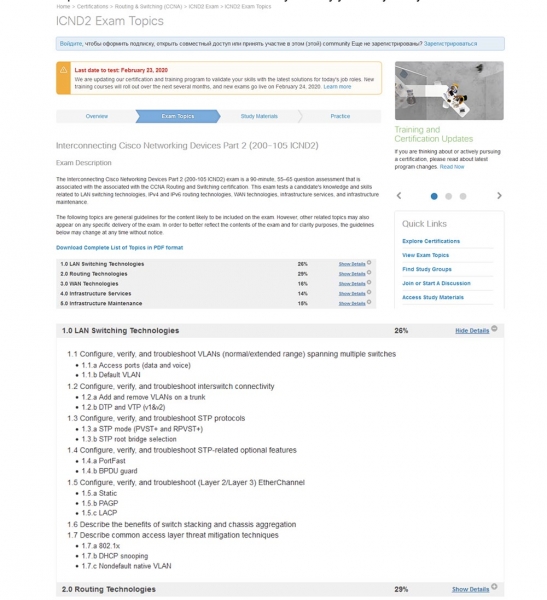
If you visit the company's website, you will see this plan and that the entire course is divided into 5 main parts:
— Local Area Network Switching Technologies (26% of the educational material);
— Routing Technologies (29%);
— Global Network Technologies (16%);
— Infrastructure Services (14%);
— Infrastructure Maintenance (15%).
I will start with the first part. If you click on the dropdown menu on the right, you can see the detailed topics of this section. Today's video lesson will cover the topic of section 1.1: 'Configuration, Verification and Troubleshooting of VLANs (Standard / Extended Range) covering multiple switches' and subsections 1.1a 'Access Ports (Data and Voice)' and 1.1b 'Default VLAN'.
Next, I will try to adhere to the same principle of presentation, meaning each video lesson will focus on one section with subsections. If there isn't enough material, I will combine the topics of several sections in one lesson, for example, 1.2 and 1.3. If there is a lot of material in a section, I will split it into two videos. In any case, we will follow the course program, and you will easily be able to compare your notes with the current Cisco curriculum.
You can see my new desktop on the screen; it is Windows 10. If you want to enhance your desktop with various widgets, you can check out my video titled 'Pimp Your Desktop,' where I explain how to customize your computer's desktop according to your needs. I post videos like this on another channel, ExplainWorld, so you can use the link in the upper right corner to explore its content.
Before we start the lesson, I would like to remind you to share my videos and give them a thumbs up. I also want to remind you of our social media contacts and links to my personal pages. You can email me, and as I mentioned, priority in receiving a personal response will be given to those who make donations on our website.
If you haven't made a donation, that's okay; you can leave your comments under the video lessons on the YouTube channel, and I will respond to them as I can.
So, today, according to the Cisco schedule, we will cover three topics: comparing Default VLAN with Native VLAN, understanding the difference between Normal VLAN (standard range VLAN) and Extended VLAN, and discussing the difference between Data VLAN and Voice VLAN. As I mentioned, we have already studied this topic in previous episodes, but rather superficially, so many students still struggle to identify the differences between VLAN types. Today, I will explain it in a way that everyone can understand.
Let's explore the difference between Default VLAN and Native VLAN. If you take a brand new Cisco switch with factory settings, it will have 5 VLANs – VLAN1, VLAN1002, VLAN1003, VLAN1004, and VLAN1005.
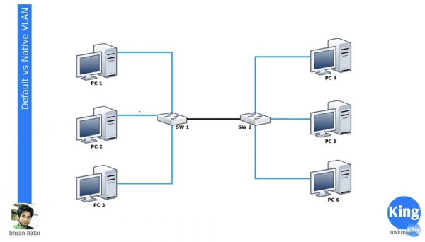
VLAN1 is the default VLAN for all Cisco devices, while VLANs 1002-1005 are reserved for Token Ring and FDDI. VLAN1 cannot be deleted or renamed, interfaces cannot be added to it, and all switch ports are part of this network by default until configured otherwise. By default, all switches can communicate with each other because they all belong to VLAN1. This is what is meant by 'default VLAN.'
If you go into the settings of switch SW1 and assign two interfaces to network VLAN20, they will become part of network VLAN20. Before starting today's lesson, I strongly advise you to review the aforementioned series 11, 12, and 13, as I will not repeat what VLANs are and how they work.
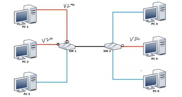
I just want to remind you that you cannot automatically assign interfaces to network VLAN20 until you create it, so you first need to enter the global configuration mode of the switch and create VLAN20. You can take a look at the CLI settings console to understand what I mean. After you have assigned these 2 ports to work with VLAN20, computers PC1 and PC2 will be able to communicate with each other because they will both belong to the same VLAN20 network. However, computer PC3 will still be part of VLAN1 and therefore will not be able to communicate with the computers on the VLAN20 network.
We have a second switch SW2, one of whose interfaces is assigned to work with VLAN20, and computer PC5 is connected to this port. With this connection scheme, PC5 cannot communicate with PC4 and PC6, but these two computers can communicate with each other since they belong to the same VLAN1 network.
Both switches are connected through trunks via appropriately configured ports. I won't repeat myself, I'll just say that all switch ports are set to trunking mode by default using the DTP protocol. If a computer is connected to a port, that port will operate in access mode. If you want to switch the port to which PC3 is connected to access mode, you will need to enter the command switchport mode access.
So, if you connect two switches to each other, they create a trunk. The two upper ports of SW1 will pass traffic only for VLAN20, the lower port will pass only traffic for VLAN1, but the trunk connection will carry all traffic passing through the switch. Thus, both VLAN1 and VLAN20 traffic will be sent to SW2.
As you may recall, VLAN networks have a local significance. Therefore, SW2 knows that traffic arriving at VLAN1 from PC4 can only be sent to PC6 through a port also belonging to VLAN1. However, when one switch sends traffic to another switch via a trunk, it must use a mechanism to inform the second switch about what type of traffic it is. This mechanism is the Native VLAN, which is connected to the trunk port and allows the passage of tagged traffic.
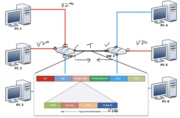
As I mentioned, a switch has only one network that is not subject to change – the default network, VLAN1. By default, the Native VLAN is VLAN1. What is Native VLAN? It is a network that allows untagged traffic from VLAN1, but as soon as traffic from any other network arrives at the trunk port, in our case VLAN20, it must be tagged. Each frame has a destination address (DA), a source address (SA), and a VLAN tag containing the VLAN ID. In our case, this identifier shows that the traffic relates to VLAN20, so it can only be sent through port VLAN20 and is destined for PC5. One could say that the Native VLAN determines whether traffic should be tagged or untagged.
Remember that VLAN1 is the default Native VLAN, as by default all ports use VLAN1 as the Native VLAN for passing untagged traffic. However, the Default VLAN is only VLAN1, the only network that cannot be changed. If a switch receives untagged frames on a trunk port, it automatically assigns them to the Native VLAN.
In simpler terms, in Cisco switches any VLAN can be used as the Native VLAN, such as VLAN20, while only VLAN1 can be used as the Default VLAN.
However, we may encounter a problem. If we change the Native VLAN for the trunk port of the first switch to VLAN20, then the port will think: "since this is the Native VLAN, its traffic doesn't need to be tagged" and will send untagged traffic from VLAN20 to the second switch. The switch SW2, upon receiving this traffic, will say: "great, this traffic has no tag. According to my settings, my Native VLAN is VLAN1, so I should send this untagged traffic over to VLAN1." Thus, SW2 will direct the received traffic only to PC4 and PC6, even though it is intended for PC5. This creates a significant security issue, as it mixes VLAN traffic. That is why both trunk ports should always be configured with the same Native VLAN; if the Native VLAN for the trunk port SW1 is VLAN20, then that same VLAN20 should be set as the Native VLAN on trunk port SW2.
This is where the difference between Native VLAN and Default VLAN lies, and you need to remember that all Native VLANs in a trunk must match (translator's note: that's why it's better to use a network other than VLAN1 as the Native VLAN).
Let's look at this from the switch's perspective. You can enter the switch and type the command show vlan brief, after which you will see that all the switch ports are connected to Default VLAN1.
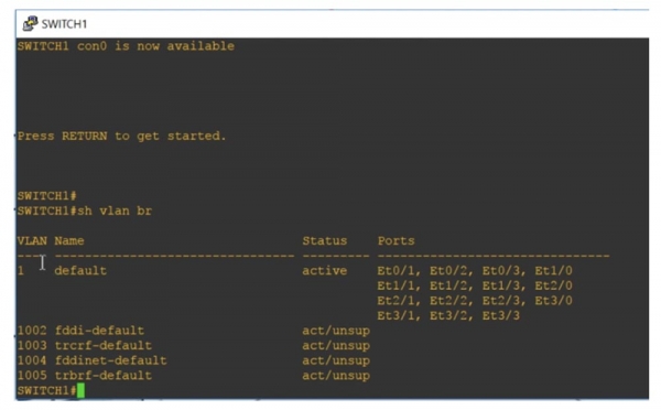
Below are four more VLANs: 1002, 1003, 1004, and 1005. These are also Default VLANs, as you can see from their designation. They are default networks because they are reserved for specific networks — Token Ring and FDDI. As you can see, they are in an active state but are not supported because networks of the mentioned standards are not connected to the switch.
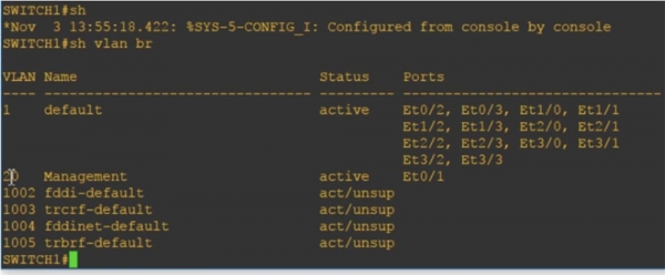
The designation "default" for VLAN 1 cannot be changed because this is the default network. Since all switch ports belong to this network by default, all switches can communicate with each other by default, meaning without the need for additional port configuration. If you want to connect a switch to another network, you enter global configuration mode and create that network, for example, VLAN20. By pressing "Enter," you will enter the settings for the created network and can assign it a name, for instance, Management, and then exit the settings.
If you use the command show vlan brief now, you will see that we have a new VLAN network called VLAN20, which is not assigned to any switch ports. To assign this network to a specific port, you need to select the interface, for example, int e0/1, access its settings, and enter the commands switchport mode access and switchport access vlan20.
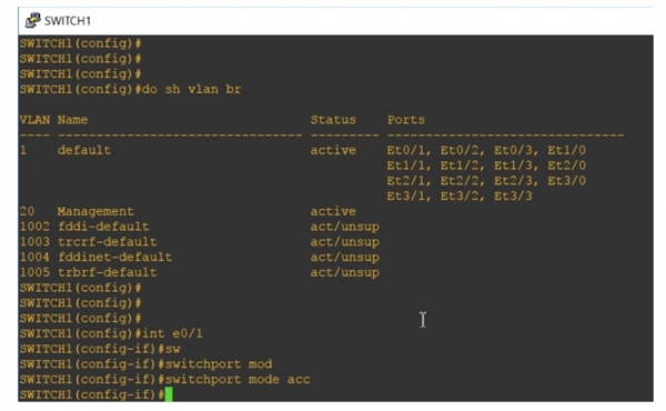
If you ask the system to show the status of VLAN networks, we will see that the Ethernet 0/1 port is now designated for the Management network, meaning it was automatically moved here from the default ports for VLAN1.
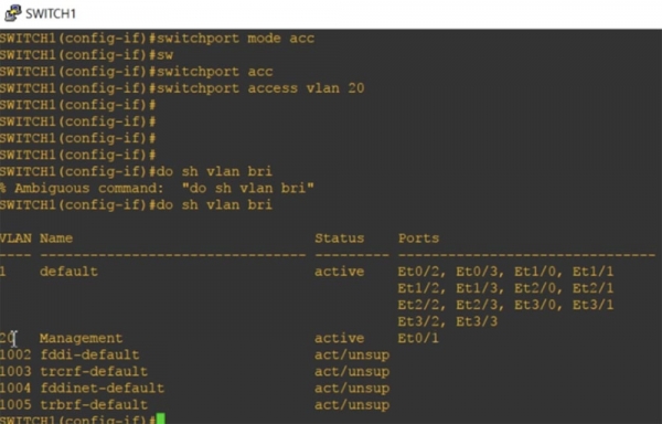
Remember that each access port can have only one Data VLAN, so it cannot serve two VLAN networks simultaneously.
Now let's look at the Native VLAN. I am using the command show int trunk and see that the Ethernet0/0 port is allocated for trunking.
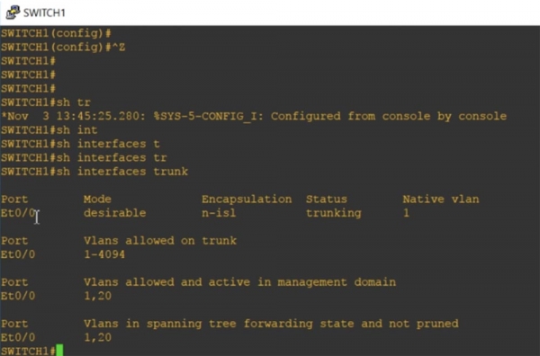
I didn't need to do this manually, as the DTP protocol automatically assigned this interface for trunking. The port is in desirable mode, encapsulation is of type n-isl, and the port state is trunking, with the Native VLAN being VLAN1.
The following is the valid range for trunking VLAN network numbers 1-4094, and it indicates that we are operating VLAN1 and VLAN20 networks. I will now enter global configuration mode and type the command int e0/0, which will take me to the settings for this interface. I am trying to manually configure this port for trunk mode using the command switchport mode trunk, but the system does not accept the command, responding that: 'the interface with automatic trunk encapsulation mode cannot be switched to trunk mode.'
Therefore, I must first configure the trunk encapsulation type, for which I use the command switchport trunk encapsulation. The system provided hints with possible parameters for this command:
dot1q — when trunking, the port uses 802.1q trunk encapsulation;
isl — when trunking, the port uses encapsulation from the proprietary Cisco ISL protocol only;
negotiate – the device performs trunking encapsulation with any device connected to this port.

At each end of the trunk, the same encapsulation type must be selected. By default, the switch 'out of the box' supports only dot1q trunking, as this standard is supported by almost all networking devices. I will configure our interface for trunk encapsulation based on this standard using the command switchport trunk encapsulation dot1q, after which I will use the previously rejected command switchport mode trunk. Now our port is set to trunk mode.
If the trunk is formed by two Cisco switches, the proprietary ISL protocol will be used by default. If one switch supports dot1q and ISL while the other supports only dot1q, the trunk will automatically switch to dot1q encapsulation mode. If we look again at the trunking options, we will see that the encapsulation mode of the interface Et0/0 has now changed from n-isl to 802.1q.
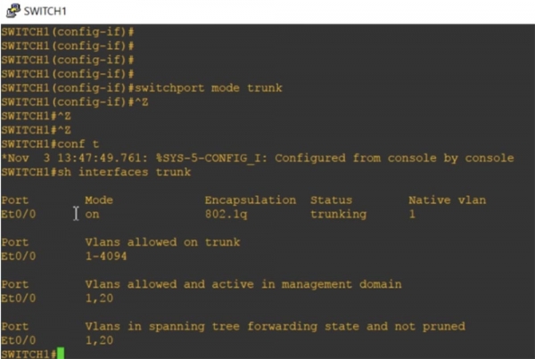
If we enter the command show int e0/0 switchport, we will see all the status parameters for this port.
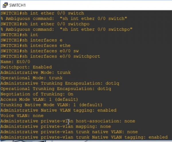
You can see that by default, VLAN1 is the 'native network' for trunking, and tagging of Native VLAN traffic is possible. Next, I use the command int e0/0, enter the settings for this interface, and type switchport trunk, after which the system provides hints for possible parameters of this command.
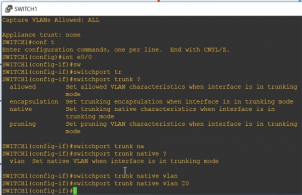
Allowed means that if the port is in trunk mode, allowed VLAN characteristics will be set. Encapsulation activates trunking encapsulation if the port is in trunk mode. I use the native parameter, which means that native characteristics will be set for the port in trunk mode, and I enter the command switchport trunk native VLAN20. Thus, in trunk mode, VLAN20 will be the Native VLAN for this port of the first switch SW1.
We have another switch, SW2, which uses VLAN1 as the Native VLAN for its trunk port. Now you see that the CDP protocol is issuing a message that there is a mismatch of the Native VLANs at both ends of the trunk: the trunk port of the first switch Ethernet0/0 uses Native VLAN20, while the trunk port of the second uses Native VLAN1. This illustrates the difference between Native VLAN and Default VLAN.
Let's proceed to examine the standard and extended range of VLAN networks.
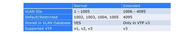
For a long time, Cisco only supported VLAN IDs ranging from 1 to 1005, with the range from 1002 to 1005 reserved by default for Token Ring and FDDI VLANs. These networks were known as standard VLANs. As you may recall, VLAN ID is a 12-bit tag that allows assigning a number up to 4096; however, for compatibility reasons, Cisco used numbers only up to 1005.
The extended VLAN range includes IDs from 1006 to 4095. It can only be used on older devices if they support VTP v3. If you are using VTP v3 and the extended VLAN range, you must disable support for VTP v1 and v2, as those versions cannot work with VLANs that have IDs greater than 1005.
So, if you are using Extended VLANs for older switches, VTP must be set to 'disable', and you need to configure VLANs manually; otherwise, VLAN database updates will not occur. If you intend to use Extended VLANs with VTP, you need to have VTP version 3.
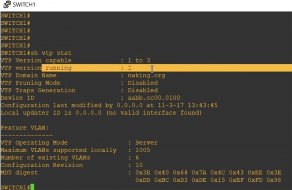
Let's check the VTP status using the command show vtp status. You see the switch is operating in VTP v2 mode, allowing support for versions 1 and 3. I assigned it the domain name nwking.org.
Here, the VTP management mode is essential – server. You can see that the maximum number of supported VLAN networks is 1005. Thus, it is clear that this switch by default supports only the standard VLAN range.
Now I will enter the command show vlan brief, and you will see VLAN20 Management mentioned here because it is part of the VLAN database.
If I now request to show the current configuration of the device with the command show run, we won't see any mention of VLANs because they are only contained in the VLAN database.
Next, I will use the command vtp mode to set the VTP operating mode. Older model switches had only three parameters for this command: client, which sets the switch to client mode, server, which enables server mode, and transparent, which puts the switch into 'transparent' mode. Since it was impossible to completely disable VTP on older switches, in this mode, the switch, while remaining part of the VTP domain, simply stopped accepting VLAN database updates coming through its ports via the VTP protocol.
The new switches have introduced the off parameter, which allows you to completely disable VTP mode. Let's switch the device to transparent mode using the command vtp mode transparent and take another look at the current configuration. As you can see, an entry for VLAN20 has now been added. Thus, if we add a VLAN network whose number falls within the normal VLAN range from 1 to 1005, and VTP is in transparent or off mode, this network will be added to the current configuration and the virtual LAN database in accordance with internal VLAN policies.
Let's try adding VLAN 3000, and you'll see it also appears in the current configuration in transparent mode. Usually, if we want to add a network from the extended VLAN range, we need to use the command vtp version 3. As you can see, both VLAN20 and VLAN3000 are shown in the current configuration.
If we exit transparent mode and enable server mode with the command vtp mode server, then look at the current configuration again, we can see that the VLAN records have completely disappeared. This happened because all VLAN information is stored only in the VLAN database and can only be viewed in VTP transparent mode. Since I enabled VTP v3 mode, after using the command show vtp status, you can see that the maximum number of supported VLANs has increased to 4096.
So, the VTP v1 and VTP v2 databases support only normal VLANs with numbers from 1 to 1005, while the VTP v3 database includes records for extended VLANs numbered from 1 to 4096. If you are using VTP transparent or VTP off mode, the VLAN information will be added to the current configuration. If you want to use the extended VLAN range, the device must be in VTP v3 mode. This is the difference between normal and extended VLANs.
Now, we will compare VLANs for data and VLANs for voice transmission. If you remember, I mentioned that each port can only belong to one VLAN at a time.
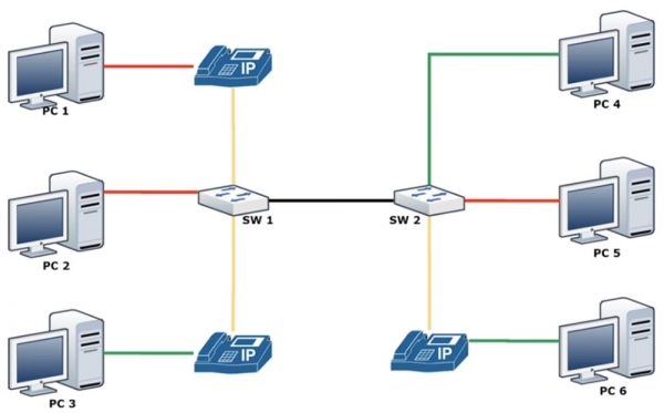
However, in many cases, we need to configure a port to work with an IP phone. Modern Cisco IP phones have a built-in switch, so you can simply connect the phone to the wall outlet with a cable and then use a patch cord to connect it to your computer. The issue is that the wall outlet, to which the phone port is connected, must have two different VLANs. We already discussed in video lessons 11 and 12 what needs to be done to prevent traffic loops, how to use the concept of 'native' VLAN to pass untagged traffic, but these were all workarounds. The final solution to the problem became the concept of separating VLANs into networks for data traffic and networks for voice traffic.
In this case, you unite all telephone lines into a voice VLAN. The diagram shows that computers PC1 and PC2 can belong to the red VLAN20 network, while computer PC3 belongs to the green VLAN30 network, but all the associated IP phones will belong to the same yellow voice network VLAN50.
In fact, each port of switch SW1 will have simultaneously 2 VLAN networks – for data and for voice.
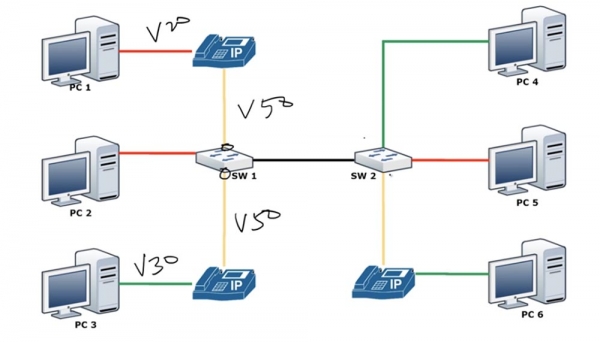
As I mentioned, access VLAN always has one VLAN; you cannot have two VLANs on one port. You cannot simultaneously apply to one interface the commands switchport access vlan 10, switchport access vlan 20, and switchport access vlan 50. However, you can use the command for the same interface two commands: the command switchport access vlan 10 and the command switchport voice vlan 50. Thus, since the IP phone contains a switch inside, it can encapsulate and send voice traffic VLAN50 while simultaneously receiving and sending in switchport access mode data traffic from VLAN20 to switch SW1. Let’s see how this mode is configured.
First, we will create network VLAN50, and then we will proceed to the settings of interface Ethernet 0/1 and program it in switchport mode access. After that, I will sequentially enter the commands switchport access vlan 10 and switchport voice vlan 50.
I forgot to configure the same VLAN mode for the trunk, so I will go to the settings of port Ethernet 0/0 and enter the command switchport trunk native vlan 1. Now I will ask to show the VLAN parameters, and you can see that now on port Ethernet 0/1 we have both networks – VLAN 50 and VLAN20.
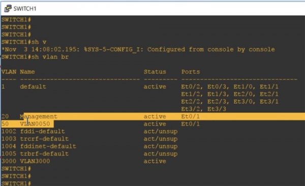
Thus, if you see that two VLANs are located on one port, it means that one of them is a Voice VLAN. This cannot be a trunk, because if you look at the trunk parameters using the command show int trunk, you can see that the trunk port contains all VLAN networks, including the default network VLAN1.
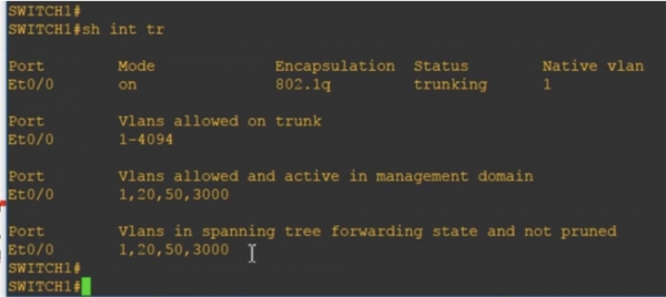
It can be said that technically, when you create a data network and a voice network, each of these ports behaves like a half-trunk: for one network, it acts as a trunk, and for the other as an access port.
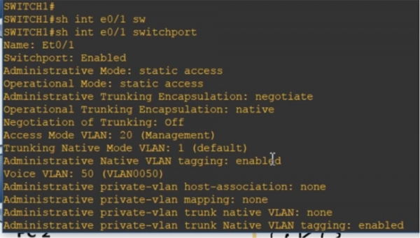
If you enter the command show int e0/1 switchport, you can see that some characteristics correspond to two operating modes: we have both static access and trunk encapsulation. In this case, the access mode corresponds to the data network VLAN 20 Management, and simultaneously, the Voice network VLAN 50 is present.
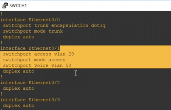
You can look at the current configuration, which will also show that this port has access vlan 20 networks and voice vlan 50.
This is the difference between Data VLAN and Voice VLAN. I hope you've understood everything I've talked about; if not, just review this video lesson again.
Thank you for staying with us. Do you enjoy our articles? Would you like to see more interesting materials? Support us by placing an order or recommending us to your friends. 30% discount for Habr users on a unique entry-level server designed by us for you: (options available with RAID1 and RAID10, up to 24 cores and up to 40GB DDR4).
Dell R730xd for half the price? Only with us in the Netherlands! Dell R420 — 2x E5-2430 2.2GHz 6C 128GB DDR3 2x960GB SSD 1Gbps 100TB — from $99! Read about how
Source: habr.com
