

Assuming that STP is in a converged state, what will happen if I take a cable and connect switch N directly to root switch A? The Root Bridge will 'see' that a new active port has come online and will send a BPDU through it.
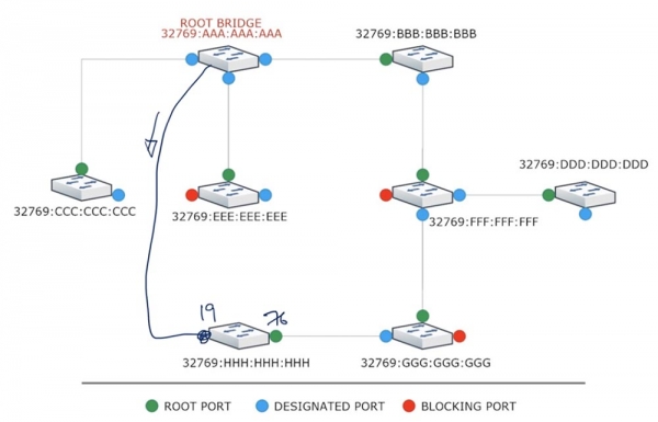
Switch N, upon receiving this frame with a cost of zero, will determine the route cost through the new port as 0+19=19, while the cost of its root port is 76. After this, switch N's previously disabled port will go through all transition stages and switch to forwarding mode in just 50 seconds. If there are other devices connected to this switch, they will all lose connection with the root switch and the network as a whole for 50 seconds.
Similarly, switch G will receive a BPDU frame from switch N notifying it of the cost of 19. It will change the cost of its designated port to 19+19=38 and reassign it as the new root port, because the cost of its previous Root Port is 57, which is greater than 38. This will restart all port reassignment stages lasting 50 seconds, and ultimately, the entire network will collapse.
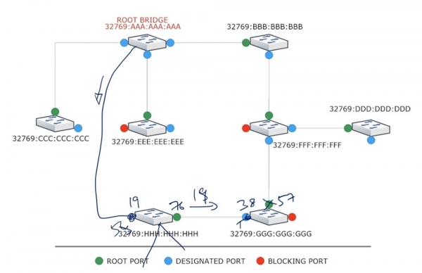
Now let's consider what will happen in a similar situation using RSTP. The root switch will also send a BPDU to the connecting switch N, but immediately after that, it will block its port. Upon receiving this frame, switch N will determine that this route has a lower cost than its root port and will block it right away. After this, switch N will send a Proposal to the root switch requesting to open a new port because its cost is lower than the cost of the existing root port. Once the root switch agrees to the request, it will unblock its port and send an Agreement to switch N, after which the latter will make the new port its root port.
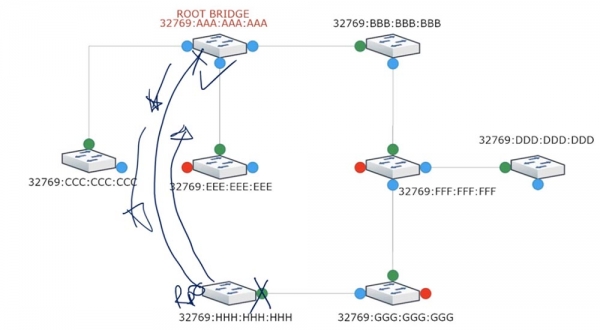
Thanks to the Proposal/Agreement mechanism, the reassignment of the root port will occur almost instantaneously, and all devices connected to switch N will not lose their connection to the network.
By designating a new Root Port, switch N will convert the old root port into an alternate port. The same will happen with switch G – it will exchange Proposal/Agreement messages with switch N, designate a new root port, and block the other ports. Then the process will continue in the next segment of the network with switch F.
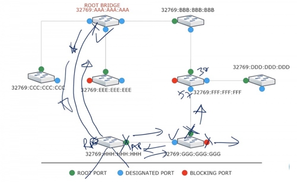
Switch F, having analyzed the costs, will see that the route to the root switch via the lower port will cost 57, while the existing route through the upper port costs 38, and will leave everything as it is. Upon learning this, switch G will block the port facing F and will start forwarding traffic to the root switch via the new route G-H-A.
Until switch F receives a Proposal/Agreement from switch G, it will keep its lower port blocked to prevent the formation of loops. Thus, you can see that RSTP is a very fast protocol that does not create network issues typical of STP.
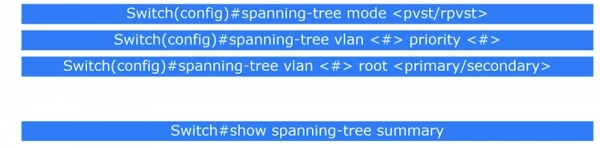
Now let's move on to reviewing commands. You need to enter global configuration mode of the switch and select either PVST or RPVST mode using the command spanning-tree mode . Then you need to decide how to change the priority of a specific VLAN. For this, use the command spanning-tree vlan priority . From the last video lesson, you should remember that the priority is a number, a multiple of 4096, and by default, it is set to 32768 plus the VLAN network number. If you chose VLAN1, then the default priority will be 32768+1= 32769.
Why might it be necessary to change the priority of networks? We know that BID consists of a numerical priority value and MAC address. The MAC address of a device cannot be changed; it has a permanent value, so only the priority value can be modified.
Assume there is a large network where all Cisco devices are interconnected in a ring topology. By default, PVST is activated, so the system will choose a root switch. If all devices have the same priority, the switch with the oldest MAC address will take precedence. However, this could be a 10-12 year old switch of an outdated model that even lacks the power and performance to 'lead' such an extensive network.
At the same time, you may have the latest switch worth several thousand dollars, which, due to its higher MAC address value, is forced to 'submit' to an old switch priced at a couple of hundred dollars. If the old switch becomes the root switch, it indicates a serious design flaw in the network.
Therefore, you should go into the settings of the new switch and assign it the minimum priority value, for example, 0. When using VLAN1, the total priority value will be 0+1=1, and all other devices will consistently see it as the root switch.
Now, let's imagine a situation. If for some reason the root switch becomes unavailable, you may want a specific switch with better network features, rather than any switch with a lower priority, to become the new root switch. In this case, the Root Bridge settings use a command that assigns the primary and secondary root switches: spanning-tree vlan root . The priority value for the Primary switch will be 32768 - 4096 - 4096 = 24576. For the Secondary switch, it is calculated using the formula 32768 - 4096 = 28672.
You don't need to input these numbers manually—the system will do this for you automatically. Thus, the switch with a priority of 24576 will be the root switch, and if it becomes unavailable, the switch with a priority of 28672 will take its place, provided that all other switches have a default priority of no less than 32768. This is what you should do if you don't want the system to automatically assign the root switch.
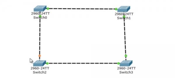
If you want to see the STP protocol settings, you need to use the command show spanning-tree summary. Now, let's review everything we studied today using Packet Tracer. I am using a network topology with 4 switches of model 2690; it doesn’t matter since all Cisco switch models support STP. They are connected in such a way that the network forms a closed loop.
By default, Cisco devices operate in PSTV+ mode, meaning that each port requires no more than 20 seconds for convergence. The simulation panel allows you to depict traffic transmission and view the operation parameters of the created network.
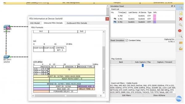
You can see what an STP BPDU frame looks like. If you see version 0, it means you are looking at STP since version 2 is used for RSTP. It also shows the Root ID value, which consists of the priority and MAC address of the root switch, and its equivalent Bridge ID value.
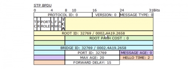
These values are equal since the cost of the path to the root switch for SW0 is 0; hence, it is itself the root switch. Therefore, after powering on the switches, the automatic selection of the Root Bridge occurred due to the use of STP, and the network started functioning. You can see that to prevent a loop, the upper port Fa0/2 of switch SW2 was set to Blocking state, but the orange marker indicates this.
Let's go to the settings console of switch SW0 and use a couple of commands. The first command is show spanning-tree, after entering which we will see information about the PSTV+ mode for the VLAN1 network on the screen. If we use multiple VLANs, another block of information for the second and subsequent networks will appear at the bottom of the window.
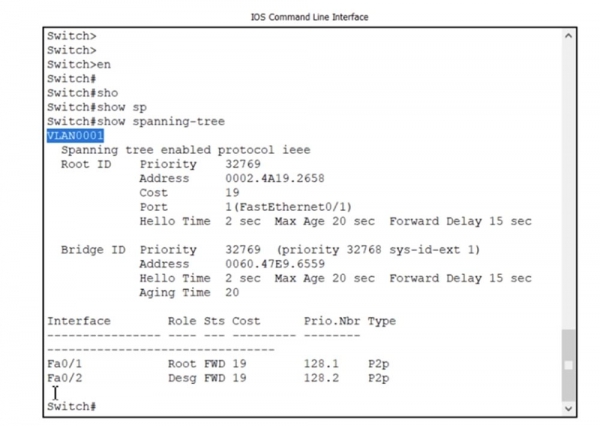
You see that the STP protocol is available under the IEEE standard, which means the use of PVSTP+. Technically, this is not standard .1d. Here we also have information on Root ID: priority 32769, the MAC address of the root device, cost 19, etc. Following this is the Bridge ID information, which decodes the value of priority 32768 +1, and another MAC address follows. As you can see, I was wrong — switch SW0 is not the root switch; the root switch has a different MAC address listed in the Root ID parameters. I think this is because SW0 received a BPDU frame with information that some switch in the network has greater grounds to play the role of root. We will examine this now.
(translator's note: Root ID is the identifier of the root switch, the same for all devices within the same VLAN network operating under the STP protocol; Bridge ID is the identifier of the local switch within the Root Bridge, which can be different for different switches and different VLANs).
Another circumstance indicating that SW0 is not the root switch is that the root switch does not have a Root Port, whereas here we have both a Root Port and a Designated Port in a forwarding state. You also see the connection type as p2p, or 'point-to-point'. This means that ports fa0/1 and fa0/2 are directly connected to neighboring switches.
If a port was connected to the hub, the connection type would be designated as shared; we'll look into this later. If I enter the command to view the summary information, show spanning-tree summary, we will see that this switch is in PVSTP mode, followed by a listing of unavailable port features.
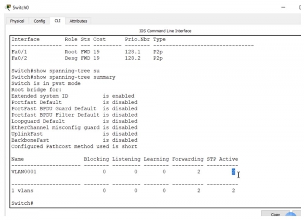
Next, the state and number of ports servicing VLAN1 are shown: blocking 0, listening 0, learning 0, with 2 ports in forwarding state under STP mode.
Before moving to switch SW2, let's look at the settings of switch SW1. For this, we use the same command, show spanning-tree.
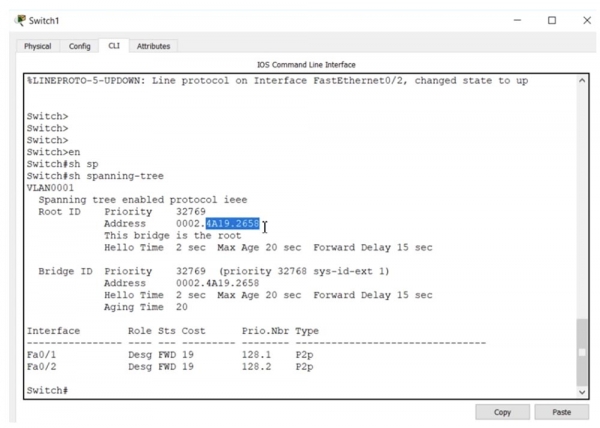
You can see that the Root ID MAC address of switch SW1 is the same as that of SW0 because all devices in the network converge to the same Root Bridge device address, trusting the choice made by the STP protocol. As you can see, SW1 is the root switch because the Root ID and Bridge ID addresses match. Furthermore, there is a message stating 'this switch is the root'.
Another sign of the root switch is that it has no Root ports; both ports are labeled as Designated. If all ports are shown as Designated and are in the forwarding state, then you are looking at the root switch.
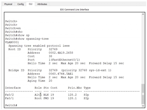
Switch SW3 contains similar information, and now I am moving to SW2 because one of its ports is in Blocking state. I use the command show spanning-tree, and we see that the Root ID information and priority value are the same as those of the other switches.
Next, it is indicated that one of the ports is Alternative. Do not be confused by this; the 802.1d standard calls it a Blocking Port, while in PVSTP, a blocked port is always referred to as Alternative. So, this alternative Fa0/2 port is in a blocked state, while port Fa0/1 acts as the Root Port.
The blocked port is located in the network segment between switch SW0 and switch SW2, preventing the formation of a loop. As you can see, the switches use a p2p type connection because no other devices are connected to them.
We have a network converging via the STP protocol. Now I will take a cable and directly connect switch SW2 to the end switch SW1. After this, all SW2 ports will be marked with orange indicators.
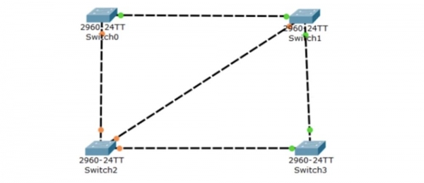
If we use the command show spanning-tree summary, we will see that initially two ports are in the Listening state, then transition to the Learning state, and after a few seconds into the Forwarding state, with the marker color changing to green. If we now enter the command show spanning-tree, we can see that Fa0/1, which was previously the Root port, has now transitioned to a blocking state and is now referred to as the Alternative port.
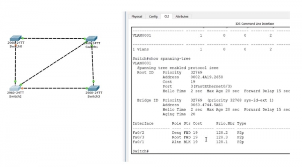
Port Fa0/3, to which the root switch cable is connected, became the Root port, while port Fa0/2 turned into the designated Designated port. Let’s revisit the convergence process. I will disconnect the SW2-SW1 cable and revert to the previous topology. You can see that the SW2 ports are first blocked and turn orange again, then sequentially transition through the Listening and Learning states, ending up in the Forwarding state. During this process, one port turns green while the other, connected to switch SW0, remains orange. The convergence process took quite a long time; these are the costs of STP operation.
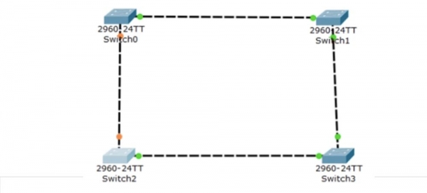
Now let’s look at how RSTP works. We will start with switch SW2 and enter the command spanning-tree mode rapid-pvst in its settings. This command has only two parameter options: pvst and rapid-pvst; I am using the latter. After entering the command, the switch transitions to RPVST mode, which can be checked with the command show spanning-tree.
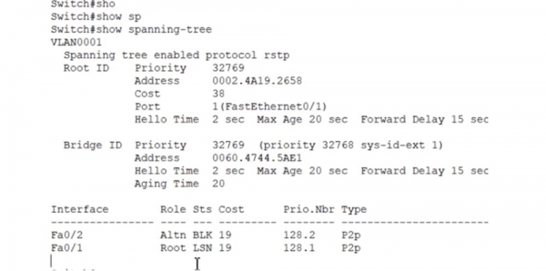
At the beginning, you see a message indicating that we are now operating under the RSTP protocol. Everything else remains unchanged. Then, I need to do the same for all other devices, and this completes the RSTP configuration. Let’s examine the operation of this protocol as we did for STP.
I am re-connecting switch SW2 directly to the root switch SW1 with a cable – let’s see how quickly convergence occurs. I enter the command show spanning-tree summary and see that two switch ports are in the Blocking state, and 1 is in the Forwarding state.
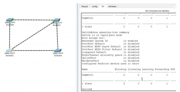
You can see that convergence happened almost instantaneously, which demonstrates how much faster RSTP is compared to STP. Next, we can use the command spanning-tree portfast default, which will switch all switch ports to portfast mode by default. This is relevant if most of the switch ports are Edge ports directly connected to hosts. If we have a port that is not an Edge, we will reset it back to spanning-tree mode.
To configure VLAN operations, you can use the command spanning-tree vlan with the parameters priority (which sets the switch priority for spanning-tree) or root (which designates the switch as the root). We use the command spanning-tree vlan 1 priority, specifying any multiple of 4096 as the priority within the range of 0 to 61440. This allows manual modification of the priority for any VLAN.
You can enter the command spanning-tree vlan 1 root with the parameters primary or secondary to set the primary or backup root port for a specific network. If I use spanning-tree vlan 1 root primary, this port will become the primary root port for the VLAN1 network.
I will enter the command show spanning-tree, and we will see that this switch SW2 has a priority of 24577, the Root ID and Bridge ID MAC addresses match, meaning it has now become the root switch.
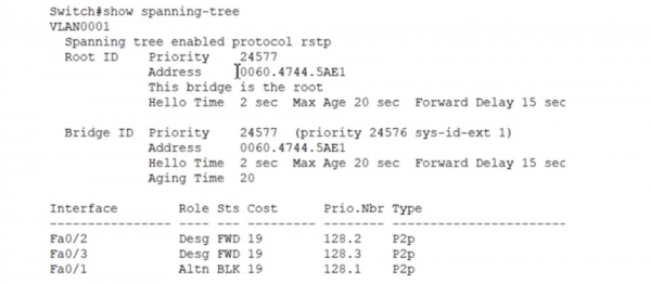
You can see how quickly the convergence and role change of the switches occurred. Now I will cancel the primary switch mode with the command no spanning-tree vlan 1 root primary, after which its priority will revert to the previous value of 32769, and the role of the root switch will return to SW1.
Let's see how portfast works. I will enter the command int f0/1, access the settings for this port, and use the command spanning-tree, after which the system will provide hints for parameter values.

Next, I will use the command spanning-tree portfast, which can be entered with the parameters disable (disabling the portfast feature for this port) or trunk (enabling the portfast feature for this port even in trunk mode).
If you enter spanning-tree portfast, the feature will simply be enabled on this port. To activate the BPDU Guard feature, you need to use the command spanning-tree bpduguard enable; the command spanning-tree bpduguard disable disables this feature.
I will quickly mention another thing. If the interface of switch SW2 towards SW3 is blocked for VLAN1, then with other configuration parameters for another VLAN, for example, VLAN2, this same interface can become the root port. Thus, a traffic load balancing mechanism can be implemented in the system – in one case, this segment of the network is unused, and in another, it is utilized.
I will show what happens when we have a shared interface upon connecting a hub. I will add a hub to the diagram and connect it to switch SW2 with two cables.
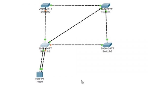
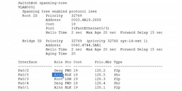
The command show spanning-tree will reflect the following picture.
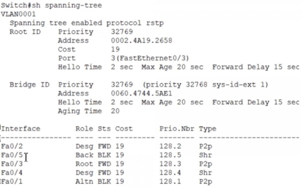
Fa0/5 (left lower port of the switch) becomes the backup port, while port Fa0/4 (right lower port of the switch) becomes the designated port. Both ports are of a shared type. This means that the segment of the hub-switch interfaces operates as a common network.
Thanks to the use of RSTP, we have a division into alternative and backup ports. If we switch SW2 to pvst mode using the command spanning-tree mode pvst, we will see that interface Fa0/5 has reverted to the Alternative state, as there is currently no distinction between the backup port and the alternative port.
It was a very long lesson, and if you didn’t understand something, I recommend reviewing it again.
Thank you for staying with us. Do you enjoy our articles? Would you like to see more interesting materials? Support us by placing an order or recommending us to your friends. 30% discount for Habr users on a unique entry-level server designed by us for you: (options available with RAID1 and RAID10, up to 24 cores and up to 40GB DDR4).
Dell R730xd for half the price? Only with us in the Netherlands! Dell R420 — 2x E5-2430 2.2GHz 6C 128GB DDR3 2x960GB SSD 1Gbps 100TB — from $99! Read about how
Source: habr.com
