

Hello, Habr. I currently serve as the course leader for "Network Engineer" at OTUS.
As we approach the start of a new course enrollment , I have prepared a series of articles on VxLAN EVPN technology.
There is an enormous amount of material available on VxLAN EVPN, so I want to compile various tasks and solutions for modern data centers.

In the first part of the series on VxLAN EVPN technology, I want to discuss a method for organizing L2 connectivity between hosts over the network fabric.
All examples will be performed on Cisco Nexus 9000v devices, arranged in a Spine-Leaf topology. We will not cover the configuration of the Underlay network in this article.
- Underlay network
- BGP peering for address-family l2vpn evpn
- NVE configuration
- Suppress-arp
Underlay network
The topology used looks as follows:
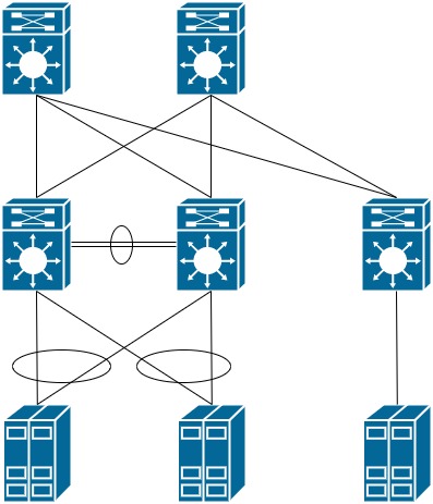
We will set addressing on all devices:
Spine-1 - 10.255.1.101
Spine-2 - 10.255.1.102

Leaf-11 - 10.255.1.11
Leaf-12 - 10.255.1.12
Leaf-21 - 10.255.1.21

Host-1 - 192.168.10.10
Host-2 - 192.168.10.20
We will check for IP connectivity between all devices:
Leaf21# sh ip route

10.255.1.11/32, ubest/mbest: 2/0                      ! Leaf-11 reachable via two Spines
    *via 10.255.1.101, Eth1/4, [110/81], 00:00:03, ospf-UNDERLAY, intra
    *via 10.255.1.102, Eth1/3, [110/81], 00:00:03, ospf-UNDERLAY, intra
10.255.1.12/32, ubest/mbest: 2/0                      ! Leaf-12 reachable via two Spines
    *via 10.255.1.101, Eth1/4, [110/81], 00:00:03, ospf-UNDERLAY, intra
    *via 10.255.1.102, Eth1/3, [110/81], 00:00:03, ospf-UNDERLAY, intra
10.255.1.21/32, ubest/mbest: 2/0, attached
    *via 10.255.1.22, Lo0, [0/0], 00:02:20, local
    *via 10.255.1.22, Lo0, [0/0], 00:02:20, direct
10.255.1.101/32, ubest/mbest: 1/0
    *via 10.255.1.101, Eth1/4, [110/41], 00:00:06, ospf-UNDERLAY, intra
10.255.1.102/32, ubest/mbest: 1/0
    *via 10.255.1.102, Eth1/3, [110/41], 00:00:03, ospf-UNDERLAY, intra
We will verify that the VPC domain is created and both switches have passed the consistency check and the configurations on both nodes are identical:
Leaf11# show vpc

vPC domain id                     : 1
Peer status                       : peer adjacency formed ok
vPC keep-alive status             : peer is alive
Configuration consistency status  : success
Per-vlan consistency status       : success
Type-2 consistency status         : success
vPC role                          : primary
Number of vPCs configured         : 0
Peer Gateway                      : Disabled
Dual-active excluded VLANs        : -
Graceful Consistency Check        : Enabled
Auto-recovery status              : Disabled
Delay-restore status              : Timer is off.(timeout = 30s)
Delay-restore SVI status          : Timer is off.(timeout = 10s)
Operational Layer3 Peer-router    : Disabled

vPC status
----------------------------------------------------------------------------
Id    Port          Status Consistency Reason                Active vlans
--    ------------  ------ ----------- ------                ---------------
5     Po5           up     success     success               1
BGP peering
Finally, we can proceed to configure the Overlay network.
In this article, we need to organize the network between hosts as shown in the diagram below:
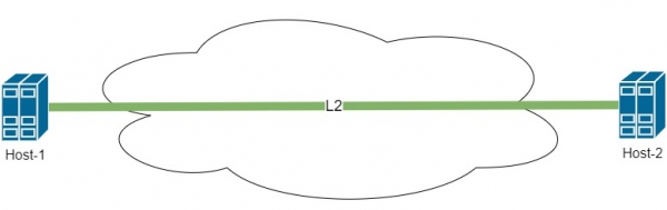
To configure the Overlay network, it is necessary to enable BGP on the Spine and Leaf switches with support for the l2vpn evpn family.
feature bgp
nv overlay evpn
Next, it is necessary to configure BGP peering between Leaf and Spine. To simplify the configuration and optimize route information dissemination, we set up Spine as a Route-Reflector server. We will list all Leaf switches in the configuration using templates to optimize the setup.
Thus, the configuration on the Spine looks like this:
router bgp 65001
  template peer LEAF
    remote-as 65001
    update-source loopback0
    address-family l2vpn evpn
      send-community
      send-community extended
      route-reflector-client
  neighbor 10.255.1.11
    inherit peer LEAF
  neighbor 10.255.1.12
    inherit peer LEAF
  neighbor 10.255.1.21
    inherit peer LEAF
The configuration on the Leaf switch looks similar:
router bgp 65001
  template peer SPINE
    remote-as 65001
    update-source loopback0
    address-family l2vpn evpn
      send-community
      send-community extended
  neighbor 10.255.1.101
    inherit peer SPINE
  neighbor 10.255.1.102
    inherit peer SPINE
On Spine, we will check the peering with all Leaf switches:
Spine1# sh bgp l2vpn evpn summary

Neighbor        V    AS MsgRcvd MsgSent   TblVer  InQ OutQ Up/Down  State/PfxRcd
10.255.1.11     4 65001       7       8        6    0    0 00:01:45 0
10.255.1.12     4 65001       7       7        6    0    0 00:01:16 0
10.255.1.21     4 65001       7       7        6    0    0 00:01:01 0
As we can see, there were no issues with BGP. Let's move on to the VxLAN configuration. Further configuration will only be performed on the Leaf switches. Spine acts only as the core of the network and is only responsible for traffic transmission. All encapsulation and path determination is done solely on the Leaf switches.
NVE configuration
NVE — network virtual interface
Before starting the configuration, let's introduce some terminology:
VTEP — Virtual Tunnel End Point, a device where a VxLAN tunnel begins or ends. A VTEP is not necessarily a specific network device. It can also be a server that supports VxLAN technology. In our topology, all Leaf switches are VTEPs.
VNI — Virtual Network Index — an identifier for the network within VxLAN. It can be likened to VLAN. However, there are some differences. When using the fabric, VLANs become unique only within one Leaf switch and are not passed across the network. However, each VLAN can be associated with a VNI number, which is then transmitted across the network. How this looks and how it can be utilized will be discussed further.
We will enable the feature for VxLAN technology operation and the ability to associate VLAN numbers with VNI numbers:
feature nv overlay
feature vn-segment-vlan-based
We will configure the NVE interface, which is responsible for the operation of VxLAN. This interface is specifically responsible for encapsulating frames into VxLAN headers. One can draw a parallel with the Tunnel interface used for GRE:
interface nve1
  no shutdown
  host-reachability protocol bgp ! we use BGP for routing information transmission
  source-interface loopback0    ! interface from which we send packets loopback0
On Leaf-21, everything is created without issues. However, if we check the output of the command show nve peers, it will be empty. Here we need to return to the VPC configuration. We see that Leaf-11 and Leaf-12 operate in a pair and are joined by the VPC domain. This leads to the following situation:
Host-2 sends a frame to Leaf-21 so that it can forward it over the network to Host-1. However, Leaf-21 sees that the MAC address of Host-1 is available through two VTEPs. How should Leaf-21 proceed in this case? This indicates that a loop may have appeared in the network.
To resolve this situation, we need Leaf-11 and Leaf-12 to act as a single device within the fabric. This can be solved quite simply. On the Loopback interface, from which we build the tunnel, we add a secondary address. The secondary address must be identical on both VTEPs.
interface loopback0
 ip add 10.255.1.10/32 secondary
Thus, from the perspective of other VTEPs, we obtain the following topology:
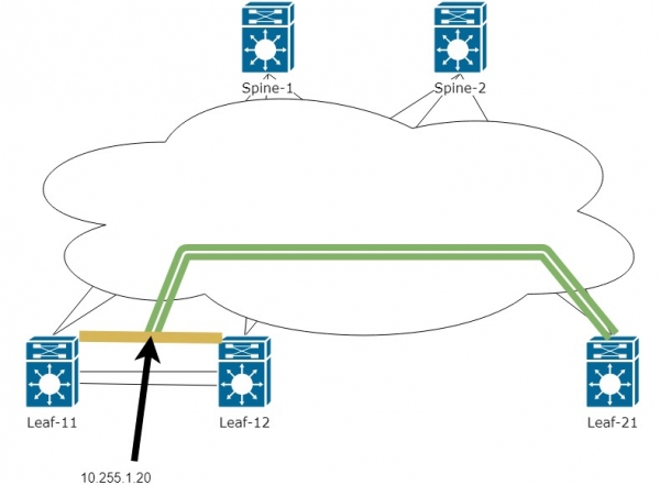
Now the tunnel will be established between the IP address of Leaf-21 and the virtual IP between the two Leaf-11 and Leaf-12. There will no longer be issues with learning the MAC address from two devices, and traffic can transition from one VTEP to another. Which of the two VTEPs will handle the traffic is determined by the routing table on the Spine:
Spine1# sh ip route

10.255.1.10/32, ubest/mbest: 2/0
    *via 10.255.1.11, Eth1/1, [110/41], 1d01h, ospf-UNDERLAY, intra
    *via 10.255.1.12, Eth1/2, [110/41], 1d01h, ospf-UNDERLAY, intra
10.255.1.11/32, ubest/mbest: 1/0
    *via 10.255.1.11, Eth1/1, [110/41], 1d22h, ospf-UNDERLAY, intra
10.255.1.12/32, ubest/mbest: 1/0
    *via 10.255.1.12, Eth1/2, [110/41], 1d01h, ospf-UNDERLAY, intra
As seen above, the address 10.255.1.10 is available through two Next-hops.
At this stage, we have addressed the basic connectivity. Let's move on to the configuration of the NVE interface:
We will immediately enable VLAN 10 and associate it with VNI 10000 on each Leaf for the hosts. We will configure an L2 tunnel between the hosts.
vlan 10                 ! Enable VLAN on all VTEPs connected to the necessary hosts
  vn-segment 10000      ! Associate VLAN with the VNI number

interface nve1
  member vni 10000      ! Add VNI 10000 for operation through the NVE interface for encapsulation in VxLAN
    ingress-replication protocol bgp    ! Specify that we use BGP for disseminating host information
Now let's check the nve peers and the BGP EVPN table:
Leaf21# sh nve peers
Interface Peer-IP          State LearnType Uptime   Router-Mac
--------- ---------------  ----- --------- -------- -----------------
nve1      10.255.1.10      Up    CP        00:00:41 n/a                 ! Peer is accessible from the secondary address

Leaf11# sh bgp l2vpn evpn

   Network            Next Hop            Metric     LocPrf     Weight Path
Route Distinguisher: 10.255.1.11:32777    (L2VNI 10000)        ! From whom this l2VNI came
*>l[3]:[0]:[32]:[10.255.1.10]\/88                                   ! EVPN route-type 3 - shows our neighbor that also knows about l2VNI10000
                      10.255.1.10                       100      32768 i
*>i[3]:[0]:[32]:[10.255.1.20]\/88
                      10.255.1.20                       100          0 i
* i                   10.255.1.20                       100          0 i

Route Distinguisher: 10.255.1.21:32777
* i[3]:[0]:[32]:[10.255.1.20]\/88
                      10.255.1.20                       100          0 i
*>i                   10.255.1.20                       100          0 i
Above we see only EVPN route-type 3 routes. This type of route describes the peer (Leaf), but where are our hosts?
The reason is that information about the MAC addresses of the hosts is transmitted via EVPN route-type 2
To see our hosts, we need to configure EVPN route-type 2:
evpn
  vni 10000 l2
    route-target import auto   ! For this article, we use an automatic number for the route-target
    route-target export auto
Let's do a ping from Host-2 to Host-1:
Firewall2# ping 192.168.10.1
PING 192.168.10.1 (192.168.10.1): 56 data bytes
36 bytes from 192.168.10.2: Destination Host Unreachable
Request 0 timed out
64 bytes from 192.168.10.1: icmp_seq=1 ttl=254 time=215.555 ms
64 bytes from 192.168.10.1: icmp_seq=2 ttl=254 time=38.756 ms
64 bytes from 192.168.10.1: icmp_seq=3 ttl=254 time=42.484 ms
64 bytes from 192.168.10.1: icmp_seq=4 ttl=254 time=40.983 ms
And below we can see that route-type 2 with the MAC addresses of the hosts — 5001.0007.0007 and 5001.0008.0007 has appeared in the BGP table.
Leaf11# sh bgp l2vpn evpn


   Network            Next Hop            Metric     LocPrf     Weight Path
Route Distinguisher: 10.255.1.11:32777    (L2VNI 10000)
*>l[2]:[0]:[0]:[48]:[5001.0007.0007]:[0]:[0.0.0.0]\/216                      !  evpn route-type 2 and MAC address of host 1
                      10.255.1.10                       100      32768 i
*>i[2]:[0]:[0]:[48]:[5001.0008.0007]:[0]:[0.0.0.0]\/216                      ! evpn route-type 2 and MAC address of host 2
* i                   10.255.1.20                       100          0 i
*>l[3]:[0]:[32]:[10.255.1.10]\/88
                      10.255.1.10                       100      32768 i
Route Distinguisher: 10.255.1.21:32777
* i[2]:[0]:[0]:[48]:[5001.0008.0007]:[0]:[0.0.0.0]\/216
                      10.255.1.20                       100          0 i
*>i                   10.255.1.20                       100          0 i
Next, you can view detailed information about the Update, in which we received information about the MAC Host. Below is not the entire output of the command.
Leaf21# sh bgp l2vpn evpn 5001.0007.0007

BGP routing table information for VRF default, address family L2VPN EVPN
Route Distinguisher: 10.255.1.11:32777        !  sent Update with MAC Host. This is not a virtual VPC address, but the Leaf address.
BGP routing table entry for [2]:[0]:[0]:[48]:[5001.0007.0007]:[0]:[0.0.0.0]\216,
 version 1507
Paths: (2 available, best #2)
Flags: (0x000202) (high32 00000000) on xmit-list, is not in l2rib\/evpn, is not in HW

  Path type: internal, path is valid, not best reason: Neighbor Address, no labeled nexthop
  AS-Path: NONE, path sourced internal to AS
    10.255.1.10 (metric 81) from 10.255.1.102 (10.255.1.102)    !  who exactly we are building the VxLAN tunnel with
      Origin IGP, MED not set, localpref 100, weight 0
      Received label 10000         ! The VNI number associated with the VLAN in which the Host is located.
      Extcommunity: RT:65001:10000 SOO:10.255.1.10:0 ENCAP:8        ! It's clear that the RT was generated automatically based on AS and VNI numbers.
      Originator: 10.255.1.11 Cluster list: 10.255.1.102
<........>
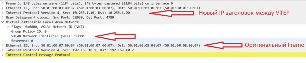
Let’s take a look at how the frames appear when they are transmitted through the fabric:
Suppress-ARP
Great, we now have L2 connectivity between hosts, and we could end here. However, it's not that simple. While we have few hosts, there won't be any problems. But let's imagine a scenario where we have hundreds or thousands of hosts. What problem might we encounter?
This problem is BUM (Broadcast, Unknown Unicast, Multicast) traffic. In this article, we will consider a way to combat broadcast traffic.
The main generator of Broadcast in Ethernet networks is the hosts themselves via the ARP protocol.
The following mechanism has been implemented on Nexus to combat ARP requests — suppress-arp.
The operation of this feature works as follows:
- Host-1 sends an ARP request to the broadcast address of its network.
- The request reaches the Leaf switch and instead of passing this request further into the fabric towards Host-2 — the Leaf responds itself, indicating the required IP and MAC.
Thus, the Broadcast request did not go to the fabric. But how can this work if the Leaf only knows the MAC address?
It's quite simple; EVPN route-type 2, besides MAC addresses, can also transmit a MAC/IP pair. For this, it's necessary to configure an IP address in the VLAN on the Leaf. The question arises: what IP should be assigned? On Nexus, there is the possibility to create a distributed (identical) address across all switches:
feature interface-vlan

fabric forwarding anycast-gateway-mac 0001.0001.0001    ! setting a virtual mac to create a distributed gateway among all switches

interface Vlan10
  no shutdown
  ip address 192.168.10.254/24          ! assign the same IP on all Leaf
  fabric forwarding mode anycast-gateway    ! specify to use Virtual mac
Thus, from the perspective of hosts, the network will look as follows:
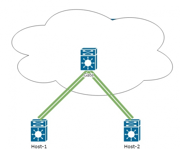
Let's check BGP l2route evpn
Leaf11# sh bgp l2vpn evpn


   Network            Next Hop            Metric     LocPrf     Weight Path
Route Distinguisher: 10.255.1.11:32777    (L2VNI 10000)
*>l[2]:[0]:[0]:[48]:[5001.0007.0007]:[0]:[0.0.0.0]/216
                      10.255.1.21                       100      32768 i
*>i[2]:[0]:[0]:[48]:[5001.0008.0007]:[0]:[0.0.0.0]/216
                      10.255.1.10                       100          0 i
* i                   10.255.1.10                       100          0 i
* i[2]:[0]:[0]:[48]:[5001.0008.0007]:[32]:[192.168.10.20]/248
                      10.255.1.10                       100          0 i
*>i                   10.255.1.10                       100          0 i


Route Distinguisher: 10.255.1.21:32777
* i[2]:[0]:[0]:[48]:[5001.0008.0007]:[0]:[0.0.0.0]/216
                      10.255.1.20                       100          0 i
*>i                   10.255.1.20                       100          0 i
* i[2]:[0]:[0]:[48]:[5001.0008.0007]:[32]:[192.168.10.20]/248
*>i                   10.255.1.20                       100          0 i
From the output of the command, it is evident that in EVPN route-type 2, besides the MAC, we now also see the host's IP address.
Let's return to suppress-arp configuration. This setting is enabled for each VNI separately:
interface nve1
  member vni 10000
    suppress-arp
Next, a certain complexity arises:
- For this feature to work, space in TCAM memory is required. Here’s an example configuration for suppress-arp:
hardware access-list tcam region arp-ether 256This configuration requires double-wide. So, if you set 256, then 512 must be freed in TCAM. The TCAM configuration goes beyond the scope of this article, as TCAM settings depend only on the tasks posed to you and may differ from one network to another.
- The implementation of suppress-arp needs to be done on all Leaf switches. However, difficulties may arise when configuring it on pairs of Leaf switches within a VPC domain. When modifying TCAM, consistency between the pairs will be disrupted, and one node may become non-operational. Additionally, a reboot of the device may be required to apply the TCAM modification.
As a result, you should carefully consider whether it's worth implementing this configuration in your working factory.
We will conclude the first part of the cycle here. In the next part, we will discuss routing through the VxLAN factory, with network segmentation using different VRFs.
And now I invite everyone to , where I will provide detailed information about the course. The first 20 participants who register for this webinar will receive a discount certificate via email within 1-2 days after the broadcast.
Source: habr.com
