

Recently, two completely different worlds converged in our lab: the world of inexpensive radio transceivers and the world of expensive wideband radio signal recording systems.
First, our good friends approached us to create software for recording signals at a bandwidth of 500 MHz. Of course, we couldn't refuse. It was necessary to do this on the board from 'Instrumental Systems', which I have known for a long time. In the early days of my engineering career, I worked with their hardware and software.
Then a dear friend came from and asked for a positioning system for drones without GPS. He said it was necessary to launch a show indoors. Moreover, nowadays, sending several million dollars into the sky on unreliable GPS is not very appealing. Interference and spoofing of satellite navigation .
For positioning without satellites with an accuracy better than ten centimeters in an area up to a kilometer, I found nothing but UWB technology. DecaWave has long been on the market, producing the DW1000 chip and modules based on it. The chip is a UWB transceiver compliant with IEEE 802.15.4-2011 standards. By the way, it is a unique piece, with a double or even triple bottom. I hope we can explore its depths over the next few years and write about it. There won't be enough time earlier.
But today we're not talking about positioning; more on that in the next episodes.
Today we are recording the DW1000 signal. And its bandwidth is none other than 1000 or 500 MHz, as determined by the channel number. 'By sheer coincidence', there was a computer with an from 'Instrumental Systems' with an FMC mezzanine from Analog Devices.
It should be noted 'for the prosecutor' that the ADC AD9208 is currently under sanctions. It cannot be legally purchased in Russia, even though it's sometimes very desirable. However, this particular module was purchased a long time ago, before the sanctions were imposed. It is as clean as a baby's soul. I hope this acknowledgment will be included in the case and will count for the defendant.
We won't go into the details of software development for recording measurement streams to the computer's memory right now. Unfortunately, we cannot publish the source code of the application for Linux at this time. However, we hope to obtain permission for this next time. It's worth noting that it wasn't straightforward, even considering the provided software developments from Instrumental Systems. The ADC itself and its clocking and output system based on JESD204B technology are quite complex to understand, and additionally, the module from AD required hardware patches. The REFCLK signal is essential for the input system, but it enters the module incorrectly into the FMC connector and, accordingly, does not reach the necessary FPGA pins. We had to apply a patch, which can be seen in the photo below — two red wires. There were indeed doubts about whether this would work. The clock frequency is high — 375 MHz, and the patch is terrible. But the system managed to cope.
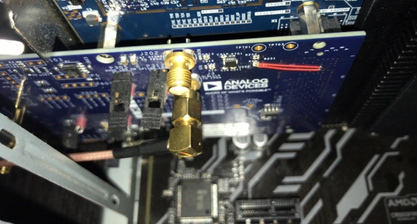
The whole setup looks like this.
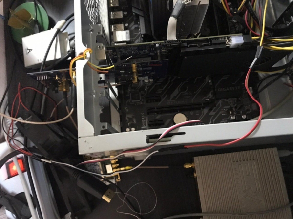
Here you can spot a computer with a good I/O system, the FMC126P board, and the AD9208-3000EBZ mezzanine. From the generators: a 3000 MHz generator for clocking the ADC and a 770 MHz generator for REFCLK. Cables with SMA connectors link the generators and deliver the input signal.
The raw data rate from the ADC output, without being picky, is 12 GB/s from two channels. According to measurements and the manufacturer's declaration of the FMC126P board, the maximum input speed is 5 GB/s. Thus, we only used one channel in the ADC and passed it through the built-in DDC (Digital Down Converter) with a decimation of four. As a result, the data stream amounted to 3 GB/s (sampling frequency of 750 MHz, 16-bit complex signal).
Checking that the system manages to record the samples is quite simple: just monitor the FIFO status stuck bits of the FPGA. If there are no FIFO Overflow events overnight, then the bit will not be set. We can happily confirm that there were no lost samples. Of course, we first ensure that the status bit capturing is working. We also examine the signal shape from the file to verify that the ADC signal quality meets the documentation.
But what kind of signal will be worthy of such an input system? Of course, UWB from the nearby table!
Fortunately, for the drone positioning system, we selected a channel frequency of 4 GHz. This corresponds to channels 4 and 2 in the DW1000 terminology (Figure 13 in the datasheet). We integrated an antenna on this frequency, or rather, on this range. Matching it over such a broad band was quite challenging. But the result turned out to be sleek! Some say it resembles a symbol... with ears.
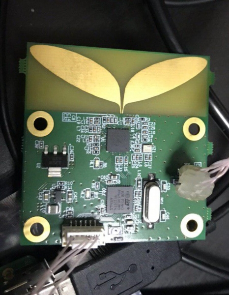
The 4 GHz signal with a bandwidth of 500 MHz falls into the third Nyquist zone and has sufficient guard intervals to avoid spectrum overlap. Therefore, we directly connected the DW1000 signal to the input of the ADC AD9208.
We received two files: one with a PRF frequency of 64 MHz and the other with 16 MHz. The transmission rate was set to the minimum for the DW1000 — 110 kbps.
This file, this is . Be careful, the files are huge!
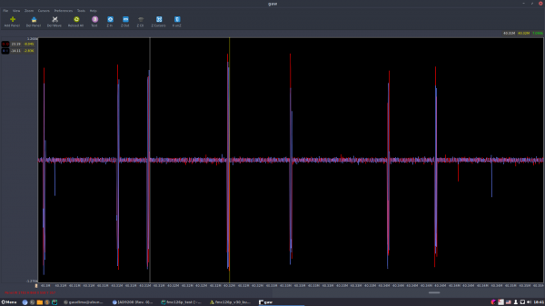
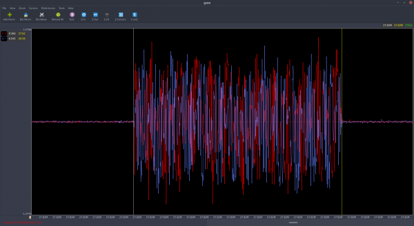
In the first file, we see packets lasting about 750 samples or 1000 nanoseconds.
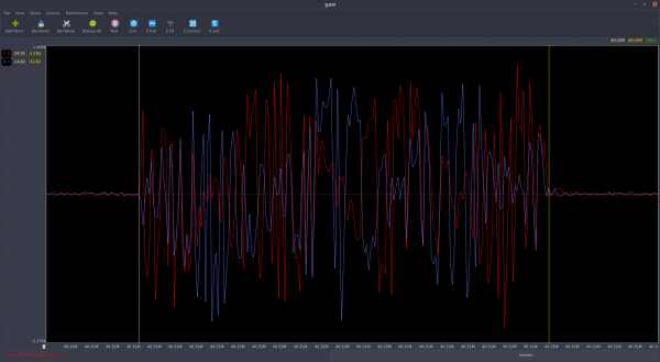
In the second file, the packets are four times shorter.
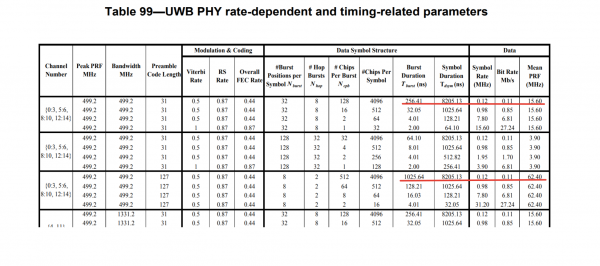
And this is entirely consistent with the IEEE 802.15.4-2011 standard concerning the UWB physical layer:
The modulation within the packet resembles phase modulation, which also aligns with that specified in the BPSK standard. You can find the standard online; search for "IEEE 802.15.4-2011."
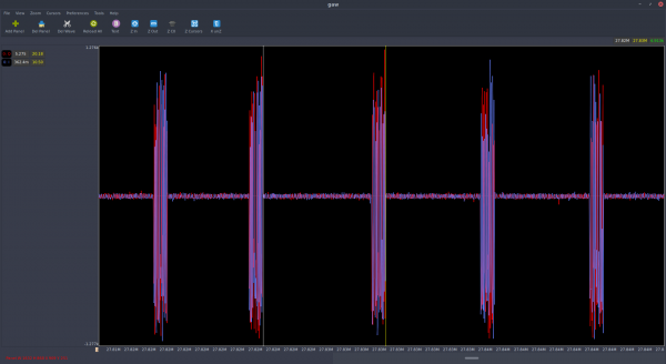
If we slightly expand the observation time window, we can also see irregularities in the packet sequence, corresponding to the description of hybrid modulation in the IEEE 802.15.4-2011 UWB — position-phase (BPM-BPSK).
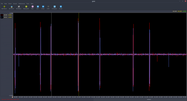
Overall, I find the DW1000 chip and the modulation of this UWB PHY to be amazing, whatever that means, comparable to military JTIDS standards. This is my new hobby. To be continued!
On one hand, we will delve into the DW1000; on the other, we will explore the IEEE 802.15.4 standard.
Source: habr.com
