

Continuing the topic , let's look at the issue of mathematical modeling from a different perspective. Once we have ensured that the model corresponds to the harsh realities of life, we can address the fundamental question: "What exactly do we have here?" In creating a model of a technical object, we typically want to ensure that this object will meet our expectations. This is why we conduct dynamic calculations of processes and compare the results with the requirements. This is what a digital twin, virtual prototype, and other trendy terms are about, which aim to solve the problem at the design stage of how to ensure that we achieve what we planned.
How can we quickly confirm that our system is indeed what we are designing—will it fly or float? If it flies, how high? If it floats, how deep?
This article examines the automation of verifying compliance with the requirements of a technical building when creating dynamic models of technical systems. As an example, let’s take a look at an element of the technical specifications for the air cooling system of an aircraft.
We consider those requirements that can be expressed numerically and verified mathematically based on a specific calculation model. Clearly, this is only part of the overall requirements for any technical system, but it is specifically on their verification that we spend time, nerves, and money to create dynamic models of the object.
When describing technical requirements in the form of documentation, we can identify several types of different requirements, each of which demands different approaches for forming automatic checks of compliance.
For example, let’s consider this small but real set of requirements:
- Ambient air temperature at the inlet of the air conditioning system:
on the ground - from minus 35 to 35 ºC,
in flight - from minus 35 to 39 ºC. - Static atmospheric pressure in flight - from 700 to 1013 hPa (from 526 to 760 mm Hg).
- Total air pressure at the inlet of the air intake system in flight - from 754 to 1200 hPa (from 566 to 1050 mm Hg).
- Cooling air temperature:
on the ground - no more than 27 ºC, for technical blocks - no more than 29 ºC,
In flight - no more than 25 ºC, for technical blocks - no more than 27 ºC. - Air cooling consumption:
at standstill - no less than 708 kg/h,
in flight - no less than 660 kg/h. - Air temperature in the instrument compartments - no more than 60 ºC.
- Amount of fine-dispersed free moisture in the cooling air - no more than 2 g/kg of dry air.
Even within such a limited set of requirements, at least two categories can be highlighted that need to be handled differently in the system:
- operating conditions requirements of the system (items 1-3);
- parameter requirements for the system (items 3-7).
Requirements of the operating conditions of the system
External conditions for the developed system during modeling can be defined either as boundary conditions or as a result of the operation of the overall system.
In dynamic modeling, it is necessary to ensure that the specified operating modes are covered by the modeling process.
Parameter requirements for the system
These requirements represent parameters provided by the system itself. During modeling, we can obtain these parameters as calculation results and ensure that the requirements are met in each specific calculation.
Identification and coding of requirements
For convenience in working with requirements, existing standards recommend assigning an identifier to each requirement. It is highly desirable to use a unified coding system when assigning identifiers.
The requirement code can simply be a number reflecting the ordinal number of the requirement, or it can include a type requirement code, a system or unit code to which it applies, a parameter code, a location code, and much more that an engineer can imagine. (For a variant of using coding, see the article)
Table 1 provides a simple example of requirement coding.
- source code of requirements R - requirements of technical specifications;
- code type of requirements E - requirements - parameters of the external environment, or operating conditions
S - requirements provided by the system; - code state of the aircraft 0 - any, G - at standstill, F - in flight;
- code type of physical parameters T - temperature, P - pressure, G - consumption, humidity H;
- ordinal number of the requirement.
| ID Requirements | Description | Parameter |
| REGT01 | The temperature of the ambient air at the inlet of the APU: at rest — from minus 35ºC to 35ºC. | |
| REFT01 | The temperature of the ambient air at the inlet of the APU: in flight — from minus 35ºC to 39ºC. | |
| REFP01 | The static pressure of the ambient air in flight ranges from 700 to 1013 hPa (from 526 to 760 mmHg). | |
| REFP02 | The total air pressure at the inlet of the APU in flight ranges from 754 to 1200 hPa (from 566 to 1050 mmHg). | |
| RSGT01 | The temperature of the cooling air: at rest, no more than 27ºC. | |
| RSGT02 | The temperature of the cooling air: at rest, for technical units no more than 29ºC. | |
| RSFT01 | The temperature of the cooling air in flight, no more than 25ºC. | |
| RSFT02 | The temperature of the cooling air: in flight, for technical units no more than 27ºC. | |
| RSGG01 | Cooling air consumption: at rest, at least 708 kg/h. | |
| RSFG01 | Cooling air consumption: in flight, at least 660 kg/h. | |
| RS0T01 | The temperature of the air in the instrument compartments no more than 60ºC. | |
| RSH01 | The amount of fine free moisture in the cooling air no more than 2 g/kg of dry air. |
Project of the requirement verification system.
For each calculated requirement, there is an algorithm for assessing the compliance of calculated parameters and the parameters specified in the requirement. Essentially, any control system always contains verification algorithms by default. Even any regulator has them. If the temperature exceeds the limit, the air conditioner is turned on. Thus, the first stage of any regulation is to check the compliance of parameters with the requirement.
And since verification is an algorithm, the same means and tools that we use to create control programs can be utilized. For example, the SimInTech environment allows the creation of project packages containing various parts of the model performed as separate projects (object model, control system model, environmental model, etc.).
In this case, the requirement verification project becomes the same project of algorithms and is connected to the model package. In dynamic modeling mode, it performs an analysis of compliance with the requirements of the specifications.
A possible example of project system design is shown in figure 1.
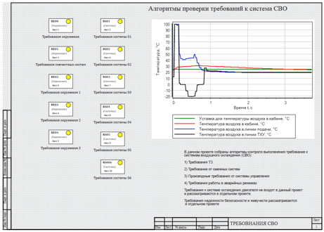
Figure 1. Example of the verification project design.
Just as for control algorithms, requirements can be formalized in the form of a set of sheets. To facilitate working with algorithms in structural modeling environments such as SimInTech, Simulink, and AmeSim, capabilities for creating multi-level structures in the form of submodels are used. This organization allows for grouping various requirements into sets to simplify working with the array of requirements, similar to what is done for control algorithms (see Fig. 2).
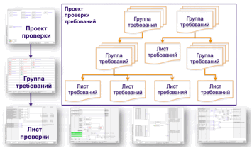
Figure 2. Hierarchical structure of the requirements verification model.
For example, in the case at hand, two groups are identified: requirements for the environment and requirements directly related to the system. Therefore, a two-level data structure is used: two groups, each of which is a leaf of the algorithm.
To connect data to the model, a standard scheme for forming a signal database is used, in which data for exchange between parts of the project is stored.
During software creation and testing, readings from sensors (analogous to actual sensors of the system) are placed into this database, which are used by the control system.
For the testing project, any parameters calculated in the dynamic model can be saved in this same database and thus used for checking compliance with requirements.
The dynamic model itself in this case can be implemented in any mathematical modeling system or even as an executable program. The only requirement is the presence of software interfaces for outputting data from the modeling to the external environment.
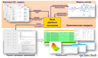
Figure 3. Connecting the verification project to the complex model.
An example of a basic requirement verification sheet is presented in Figure 4. From the developer's perspective, it represents a regular calculation scheme, visually depicting the requirement verification algorithm.
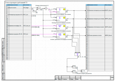
Figure 4. Requirement verification sheet.
The main parts of the verification sheet are described in Figure 5. The verification algorithm is formed similarly to the calculation schemes of control algorithms. On the right side is the block for reading signals from the database. In this block, access to the signal database occurs during modeling.
The received signals are analyzed to determine the conditions for checking requirements. In this case, height analysis is performed to determine the aircraft's position (whether it is on the ground or in flight). Other signals and calculated model parameters can also be used for this purpose.
The verification conditions and parameters to be checked are passed to standard verification blocks, where the analysis of these parameters is performed to ensure compliance with the specified requirements. The results are recorded in the signals database in such a way that they can be used for automatic checklist generation.
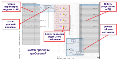
Figure 5. Structure of the requirements verification calculation sheet.
As verified parameters, it is not necessary to use signals contained in the database, which are controlled by parameters calculated during the modeling process. There is nothing preventing additional calculations within the requirements project, just as we calculate the verification conditions.
For example, such a requirement:
The number of activations of the correction system during flight to the target must not exceed 5, and the total operating time of the correction system must not exceed 30 seconds.
In this case, a counter algorithm for the number of activations and total operating time is added to the requirements project calculation scheme.
Standard verification block for requirements.
Each standard verification block is designed to calculate the fulfillment of a specific type of requirement. For example, the environmental requirements include a range of permissible ambient air temperatures both on the ground and in flight. This block must receive the air temperature from the model as a parameter and determine whether this parameter falls within the specified temperature range.
The block contains two input ports, param and condition.
The first port receives the parameter to be verified. In this case, it is 'External air temperature.'
The second port receives a boolean variable – a condition for performing the check.
If TRUE (1) is received at the second input, the block performs the requirement verification calculation.
If the second input is FALSE (0), the verification conditions are not executed. This is necessary to account for calculation conditions. In our case, this input is used to enable or disable the verification depending on the state of the model. If the aircraft is on the ground during modeling, flight-related requirements are not checked, and vice versa – if the aircraft is in flight, requirements related to ground operations are not checked.
This input can also be used when configuring the model, for example, at the initial stage of the calculation. When the model is brought to the required state, the verification blocks are disabled, but as soon as the system reaches the required operating mode, the verification blocks are activated.
The parameters of this block are:
- boundary conditions: upper (UpLimit) and lower (DownLimit) limits of the ranges that need to be checked;
- the required hold time of the system at the boundary ranges (TimeInterval) in seconds;
- requirement identifier ReqName;
- allowable out-of-range Out_range – a boolean variable that determines whether a value exceeding the checked range is a requirement violation.
In some cases, exceeding the checked value means that the system has a margin and can operate outside the working range. In other cases, exceeding means that the system cannot maintain the specified parameters within the range.
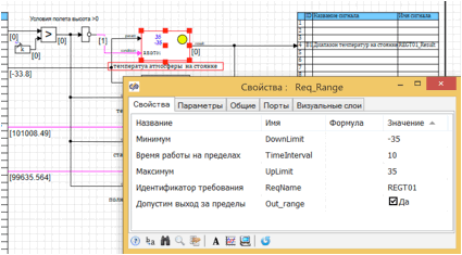
Figure 6. A typical property check block in the diagram and its parameters.
As a result of the calculation of this block, the output variable Result is generated, which takes the following values:
- 0 – rNone, value is undefined;
- 1 – rDone, requirement is met;
- 2 – rFault, requirement is not met.
The block image contains:
- identifier text;
- numerical displays of measurement limit parameters;
- color identifier of parameter status.
Inside the block, there can be a quite complex logical output scheme.
For example, to check the working temperature range of the block shown in Figure 6, the internal schematic is presented in Figure 7.
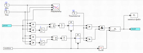
Figure 7. Internal schematic of the temperature range definition block.
Inside the block, the properties defined in the block parameters are used.
In addition to requirements compliance analysis, the internal block scheme includes a chart necessary for displaying simulation results. This chart can be used both for viewing during the calculation and for analyzing results after the calculation.
The calculation results are output from the block and simultaneously written to a common report file, which is created based on the results across the entire project. (see Fig. 8)
An example of a report created based on simulation results is an HTML file generated according to a specified format. The format can be freely customized to the one accepted by a specific organization.
Inside the block, the properties defined in the block parameters are used.
In addition to requirements compliance analysis, the internal block scheme includes a chart necessary for displaying simulation results. This chart can be used both for viewing during the calculation and for analyzing results after the calculation.
The calculation results are output from the block and simultaneously written to a common report file, which is created based on the results across the entire project. (see Fig. 8)
An example of a report created based on simulation results is an HTML file generated according to a specified format. The format can be freely customized to the one accepted by a specific organization.
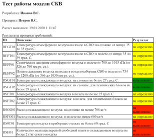
Figure 8. Example of a report file based on simulation results.
In this example, the report form configuration is performed directly in the project properties, while the format is set in the table as global project signals. In this case, SimInTech itself resolves the task of configuring the report, and the result writing block uses these strings to write to the report file.
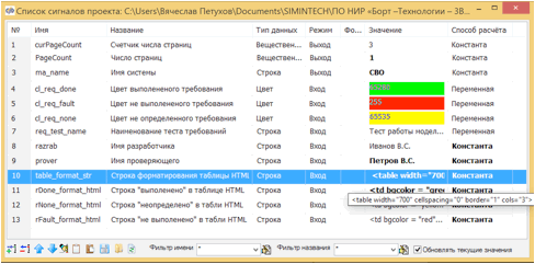
Figure 9. Report format configuration in global project signals.
Using a signal database for requirements.
To automate work with property settings for each standard block, a standard structure is created in the signal database. (see Fig. 10)
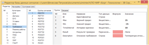
Figure 10. Example structure of a requirement verification block in the signal database.
The signal database provides:
- Storage of all necessary parameters of system requirements.
- Convenient viewing of existing requirements in the project based on specified parameters and current simulation results.
- Configuration of a single block or a group of blocks using a scripting programming language. Changes in the signal database lead to changes in the block property values on the scheme.
- Storage of text descriptions, links to sections of the relevant document, or identifiers in the requirements management system.
The structures of signal databases for requirements can be easily configured to work with third-party requirements management systems. The overall interaction scheme with requirements management systems is presented in Figure 11.
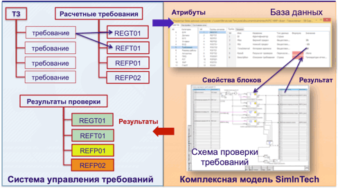
Figure 11. Interaction scheme with the requirements management system.
The sequence of interaction of the test project SimInTech with the requirements management system is as follows:
- The technical specification is divided into requirements.
- Requirements from the technical specification that can be verified through mathematical modeling of technical processes are identified.
- The attributes of the identified requirements are transferred to the SimInTech signal database in typical block structures (for example, maximum and minimum temperature).
- During the calculation, the structure data is transferred to the block calculation schemes, an analysis is performed, and the results are saved to the signal database.
- Upon completion of the calculation, the analysis results are transferred to the requirements management system.
Steps 3 to 5 in the requirements process can be repeated during the design process when changes occur in the design and/or requirements, necessitating re-checking the impact of the changes made.
Conclusions.
- The created system prototype significantly reduces the time required to analyze existing models for compliance with the requirements of the technical specification.
- The proposed testing technology uses already existing dynamic models and can be applied even to any dynamic models, including those developed outside the SimInTech environment.
- Using batch data organization allows for creating requirement verification packages in parallel with model development, or even using these packages as technical specifications for model development.
- The technology can be integrated with existing requirements management systems without significant costs.
For those who have read to the end,
Source: habr.com
