

The enterprise has purchased monitoring posts NEXST-M of domestic production from 'Next Technologies'. They are designed to visualize the operation of pump units,
fire and security alarms, voltage presence at starters, indoor temperature, and emergency water levels. The heart of NEXST-M is the ATMEGA 1280, which offered optimism regarding the creation of a custom set for specific needs.
The task was set to create a fully autonomous local dispatching system for specific needs in the shortest possible time and with minimal costs. The foundation is a microcontroller. Development and manufacturing are being carried out by the staff themselves.
The system should operate independently of cellular networks, servers, the internet, and the permissive system for using radio frequency resources, avoiding the use of computers in control and management systems or at most periodic use of laptops, without access to sites for extended periods (6-9 months). The network configuration has a radial structure. Data is collected at a single point and then sent for processing through ordinary communication channels or in the form of a hard copy.
The system must provide:
- monitoring of pump installation operations
- technological automation
- protection against the consequences of emergency modes
- signalization of emergency modes
- tracking of operating time
- tracking of electricity consumption
- monitoring of equipment temperature
- security and fire alarm systems
- periodic remote information collection
- unknown requirements in the future
Operating conditions:
- coverage area of 1 sq. km.
- direct visibility between objects
- temperature from +50 to -50°C
- humidity up to 100%
- biologically active deposits (mold, sulfate-reducing bacteria)
- vibration, no more than machines of class 1-2 according to GOST ISO 10816-1-97
- electromagnetic environment - switching of electric motors with contactors KT 6053, soft start equipment RVS-DN, PID control equipment SIEMENS MICROMASTER, emissions in the ISM and GSM bands according to the requirements for these devices, manual arc welding on site.
- excessive network voltage, brief interruptions in power supply, lightning surges, phase imbalance during a power line break in 6-10 kV distribution networks.
Despite such strict requirements, implementation is quite straightforward when tackling the task step by step.
Taking everything into account, the 'brain' of the devised system became the 'Arduino Nano 3.0' board. The board from 'Robotdyn' features the ATMEGA 328 controller, and the necessary 3.3V voltage stabilizer for
800 mA current and a CH340G UART-USB converter.
First and foremost, counters for operating time were created as the most relevant. Previously used industrial counters built on PICs with non-transformer power supply schemes failed due to voltage spikes during a year of operation. Only those connected through homemade 5V power supplies remained intact. To speed up installation and facilitate universal connectivity, the status signal of the aggregates is taken from the terminals of switching devices, i.e., registering the presence of the first phase of voltage in a three-phase 380V power supply. An intermediate relay with a 220V coil or an optocoupler made of a light-emitting diode and a GL5516 photoresistor or a PC817 optocoupler is used for interfacing with the controller. All variants were tested in operation. The light-emitting diode is powered by rectified voltage with current limitation using two capacitors SVV22 rated for 630V connected in series for safety during accidental testing of the circuits with a megohmmeter.
Reading operating time readings using an ST7735S LCD screen, real-time data transmission via radio channel with the E01-ML01DP05 module at a frequency of 2.4 MHz. This device contains the nRF24L01+ chip and the RFX2401C transceiver amplifier,
with an output power of up to 100 mW. The antennas are spiral, designed for the required range in an online calculator. The selection of antenna types is determined by the exclusion of receiving reflections from surrounding metal structures. The antenna components are printed using a 3D printer. The current state of the counters is saved in the EEPROM of the controller and restored in the event of unexpected power loss. The time intervals for counting are provided by the RTC chip DS3231 in the form of a module with a backup battery. The power supply uses 3 modules: the main impulse source 220/5V HLK-PM01 600mA, and a converter from 1-5V to 5V. and — a battery controller that has for protection against short circuits, over-discharge, and overcharging. All components were purchased from Aliexpress.
Breadboard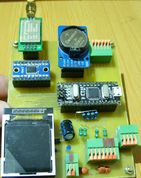
4-channel counter. LC filters are installed on the inputs for protection against interference on the communication line from twisted pair. Data on the state of control objects is continuously read once per second and displayed in color on the LCD. The updates and recording to non-volatile memory occur every 36 seconds. 36 seconds is 1/100 of an hour, which is the required format for the data. Every 12 seconds, information about the number of seconds of operation for each control unit is transmitted. The EEPROM has a limited number of write-erase cycles, according to the manufacturer’s data, 100,000 times. The worst-case scenario is when at least one cell is constantly being updated. The volume of one counter is 4 bytes, which is a long format number; 4 counters, thus 16 bytes are used for one record. The length of the chip memory is 1024 bytes; after 64 records of 4 counters, the recording will start again. In the EEPROM library, the EEPROM.put method does not perform writing if the cell value and the information being written match, so there will be no cell degradation. As a result, the guaranteed operational time of the memory will be more than 7 years. The possible but non-guaranteed operational time may be much longer.
Schematic diagram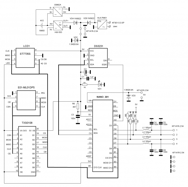
Program in Arduino IDE//12 328 байт (38%)
#include <Adafruit_GFX.h> // Core graphics library
#include <Adafruit_ST7735.h> // Hardware-specific library
#include <SPI.h>
#include <EEPROM.h>
#include <Wire.h>
#include <nRF24L01.h>
#include <RF24.h>
RF24 radio(9, 10); // radio object for working with the RF24 library,
// и номера выводов nRF24L01+ (CE, CSN)
#include <DS3231.h>
DS3231 rtc(SDA, SCL);
Time t;
//#define TFT_CS 10
#define TFT_CS 8
#define TFT_RST -1 // you can also connect this to the Arduino reset
// in which case, set this #define pin to -1!
//#define TFT_DC 9 // DC=RS=A0- варианты обозначений вывода выбора регистра команд или данных.
#define TFT_DC 3
Adafruit_ST7735 tft = Adafruit_ST7735(TFT_CS, TFT_DC, TFT_RST);
// Option 2: use any pins but a little slower!
#define TFT_SCLK 13 // set these to be whatever pins you like!
#define TFT_MOSI 11 // set these to be whatever pins you like!
//Adafruit_ST7735 tft = Adafruit_ST7735(TFT_CS, TFT_DC, TFT_MOSI, TFT_SCLK, TFT_RST);
#include <avr/wdt.h>
byte shift = 52;
byte pinState;
unsigned long pump[4]; // array with 4 counter values in seconds
float m = 3600.0;
unsigned int address = 0;
int rc; // variable for counters
unsigned long sumprim = 0;
unsigned long sumsec = 0;
byte i = 0;
byte k = 34;
unsigned int z = 0;
byte b = B00000001;
byte pumrcounter [4]; // array for storing the states of objects, 1- off, 0- on.
int start = 0; //
void setup() {
rtc.begin();
radio.begin(); // Initialize nRF24L01+ operation
radio.setChannel(120); // data transmission channel (0 to 127).
radio.setDataRate(RF24_250KBPS); // data transmission speed (RF24_250KBPS, RF24_1MBPS, RF24_2MBPS).
radio.setPALevel(RF24_PA_MAX); // transmitter power (RF24_PA_MIN=-18dBm, RF24_PA_LOW=-12dBm,
// RF24_PA_HIGH=-6dBm, RF24_PA_MAX=0dBm)
radio.openWritingPipe(0xAABBCCDD11LL); // Opening a pipe with the identifier for data transmission
// Для установки времени- раскомментировать нужные строки
//rtc.setDOW(1); // День недели
//rtc.setTime(21, 20, 0); // Время, в формате 24 часа.
//rtc.setDate(29, 10, 2018); // Дата, 29 октября 2018г.
tft.initR(INITR_BLACKTAB); // Initialize a ST7735S chip, black tab
// Use this initializer (uncomment) if you’re using a 1.44" TFT
//tft.initR(INITR_144GREENTAB); // initialize a ST7735S chip, RED rcB tab
tft.setTextWrap(false); // Allow text to run off the right edge
tft.setRotation(2); // for BLACK PCB and RED tft.setRotation(0) or not.
tft.fillScreen(ST7735_BLACK); // Clear the screen
DDRD = DDRD | B00000000;
PORTD = PORTD | B11110000; // software pull-up is working, high level-
// контролируемые объекты «не работают», во все 4 старших порта D записана «1», не идет счет.
for (rc = 0; rc < 4; rc++)
{
tft.setCursor(3, rc * 10 + shift); // Display object control position numbers
tft.print(rc + 1);
}
tft.setCursor(12, 0); // Output 3 lines of text
tft.println("DEVELOPERS & BUILD"); // To praise ourselves
tft.setCursor(24, 10); // or a malicious copyright
tft.print("DEVELOPER M.M.");
tft.setCursor(28, 20);
tft.print("BUILD-ER D.D.");
//восстановление данных/////////////////////////////////////////////////////////
for (z = 0; z < 1023; z += 16) { // Iterating through all EEPROM cells
//и записывает в массив из 4-х переменных pump, по 4 байта каждый счетчик, т.к.
// переменная беззнаковая лонг. Счетчиков 4, одна запись всех 4-х занимает 16 байт.
EEPROM.get(z, pump[0]); // So, without a for loop, less volume
EEPROM.get(z + 4, pump[1]);
EEPROM.get(z + 8, pump[2]);
EEPROM.get(z + 12, pump[3]);
// присвоение нового очередного значения суммы 4-x счётчиков
sumprim = (pump[0] + pump[1] + pump[2] + pump[3]);
// сравнивается новое значение суммы 4-х счетчиков в переменной sumprim с предыдущим значением в переменной
// sumsec и если предыдущая сумма меньше или равна новой сумме, присваивается новое большее или равное
// sumsec значение.
if (sumsec <= sumprim) {
sumsec = sumprim; //
//и присваивается переменной address текущее значение z, z- это адрес начала блока в 16 байт из 4-х значений
// счетчиков, записанных в одно и то-же время ( т.к. при опросе порта записываются одновременно все его 8 бит,
// в том числе наши нужные старшие 4 бита порта D).
address = z;
}
}
// еще раз обращение к памяти еепром по адресу начала блока в 16 байт из 4-х значений счетчиков записанных
// последними, т.е. значения перед выключением или перезагрузкой по причине зависания. Запись последних
// значений счетчиков в массив из 4-х переменных pump.
EEPROM.get(address, pump[0]);
EEPROM.get(address + 4, pump[1]);
EEPROM.get(address + 8, pump[2]);
EEPROM.get(address + 12, pump[3]);
address += 16; // Increase address for writing the next block without overwriting the last record
// конец восстановления данных////////////////////////////////////////////////////////////////
attachInterrupt(0, count, RISING); // pin D2, enable interrupt operation, arrives every second
// импульсы от RTC DS3231 с выхода SQW
wdt_enable(WDTO_8S); // start the watchdog timer, resets the controller in case of hanging, time,
// за которое надо подать команду сброса таймера wdt_reset( и избежать перезагрузки при нормальной работе- 8 сек.
// для тестов не рекомендуется устанавливать значение менее 8 сек.В данном случае сброс таймера происходит в пре-
// рывании, а оно каждую секунду.
}
void loop() {
// пустой цикл, здесь будет контроль за неполнофазным режимом работы эл.двигателя
}
void count() {
tft.setTextColor(ST7735_WHITE); // setting the font color
t = rtc.getTime(); // reading time
tft.setCursor(5, 120); // setting the cursor position
tft.fillRect(5, 120, 50, 7, ST7735_BLACK); // clear the time output area
tft.print(rtc.getTimeStr()); // output clock readings
wdt_reset(); // reset the watchdog timer every cycle, i.e., every second
for (rc = 0; rc < 4; rc++) // start of the cycle checking the input state matching
// битов порта предыдущему считанному состоянию битов порта D
{
pinState = (PIND >> 4) & (b << rc);
if (pumrcounter[rc] != pinState) { // and if not matching, then
pumrcounter[rc] = pinState; // assigns the port bit state variable a new value 1/0
}
// индикация состояния объектов контроля цветом
// BLUE- это небольшой глюк имеющегося экрана ( или библиотеки? ), перепутаны RGB и BGR.
if (pinState == (b << rc)) {
tft.fillRect(15, ((rc * 10 + shift)), 7, 7, ST7735_BLUE); // to count in low state change GREEN to BLUE
} else {
tft.fillRect(15, ((rc * 10 + shift)), 7, 7, ST7735_GREEN); // to count in low state change BLUE to GREEN
pump[rc] += 1; // incrementing the time operation counter by 1 second
}
}
k++;
if (k == 36) {
k = 0;
tft.fillRect(30, shift, 97, 40, ST7735_BLACK); // clear the area for output time operation
tft.fillRect ( 60, 120, 73, 7, ST7735_BLACK); // and dates
tft.setCursor ( 60, 120 ); // setting the cursor position
tft.print(rtc.getDateStr()); // displaying the date on the LCD screen
for (rc = 0; rc < 4; rc ++) // displaying readings in whole, tenths, and
{
tft.setCursor ( 30, rc * 10 + shift ); // hundredths of an hour with a downward shift of 10 pixels on the screen
tft.println(pump [rc] / m);
}
// запись «сырых» значений наработки (в секундах)в EEPROM //////////////////////////////
for (rc = 0; rc < 4; rc ++)
{
EEPROM.put(address, pump [rc]);
address += sizeof(float); // incrementing the write address variable
}
}
// отправляем данные по радиоканалу из data указывая сколько байт надо отправить.
if ((k == 6) || (k == 18) || (k == 30)) {
unsigned long data;
radio.write(&start, sizeof(start));
for ( i = 0; i < 4; i ++) {
data = pump [i ];
radio.write( &data, sizeof( data));
}
}
}
A few remarks at the end. Counting starts with a low logical level on the inputs.
Pull-up resistors R2-R5 are 36 kΩ for the version with GL5516 photoresistors. For the phototransistor optocoupler and relay, use 4.7-5.1 kΩ. The Arduino Nano v3.0 bootloader has been replaced with Arduino Uno using TL866A programmer for proper operation of the watchdog timer. The fuses have been adjusted to operate at voltage above 4.3 V. The external reset circuit R6 C3 was not used. In the program example, the transmitter frequency does not correspond to the unlicensed range, the 2.4 GHz range is limited to frequencies 2400.0—2483.5 MHz.
The transmitter range E01-ML01DP05 is 2400-2525 MHz. The bandwidth of one channel is 1 MHz; setting the speed to 'RF24_2MBPS' will occupy the specified radio.setChannel(120) channel and the next, i.e., the bandwidth will be 2 MHz.
Source: habr.com
