

Start on this site .
The most convenient way to gather information about the starter's activation turned out to be the option with the optocoupler PC817. Schematic diagram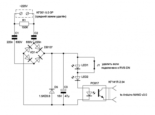 The boards contain three identical circuits, all housed in ABS plastic boxes, measuring 100x100 mm. Photo of the optocoupler
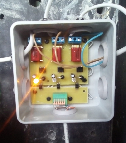 When connected to starters with semiconductor switches, their leakage current is sufficient to trigger the PC817, causing a false activation of the counter. To avoid this situation an additional LED is added in series with the input optocoupler LED and the operation indication LED. For this purpose, the jumper J1 is opened and an additional LED LED1 is soldered.
The receiving part is implemented on side 1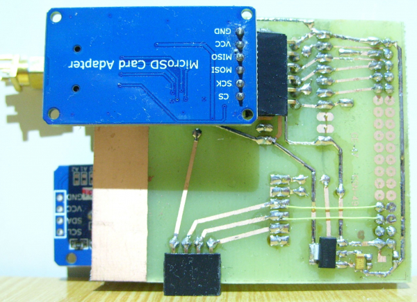 side 2
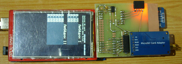
 a prototype board connected to the ARDUINO MEGA 2560. A dual-row connector on the edge is used for this. A resistive touch screen with a temperature sensor and a resolution of 240x400 is used as the information display device HX8352B.
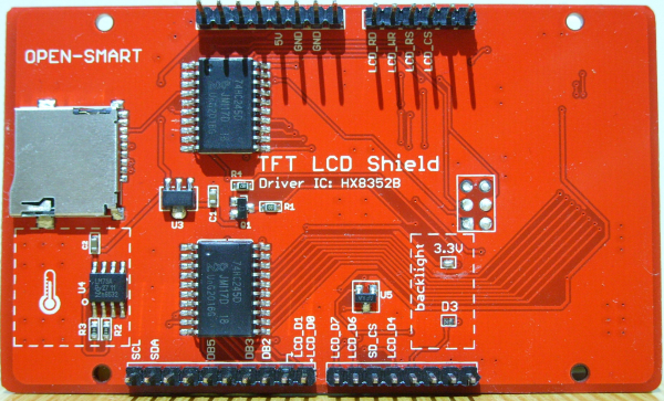 Moreover, the connector to the ICSP on the screen board has been removed and the micro-SD socket is not used. The reason is that the 'native' SD socket cannot be used due to a conflict on the SPI bus. A separate card reader, which includes a 3.3V regulator and a buffer chip with three output states 74LVS125A, was used for the flash card. Here I faced some difficulties. The buffer with three states worked either with E01-ML01DP5 or the card reader. In the comments of the SdFat library, I noticed a warning about incompatibility with other devices. The level converter TXS0108E was removed and replaced with jumpers since E01-ML01DP5 is tolerant to 5V signals — it didn't help. Using an oscilloscope, I found that the signal on the MISO line disappeared when the card reader was connected. Upon closer examination, it was determined that the enable signal inputs of the four channels of the 74LVS125A were simply soldered to the common wire, and there could be no mention of a third state. The buffer chip was used as a primitive level converter from 5V to 3.3V using resistors of 3.3 kOhm connected in series with the signal lines, except for the MISO line. Its output lower switch likely pulled the signals down to the 'ground' level. Having determined that the enable signal for the MISO line is pin 13, it was cut from the track andsoldered back.
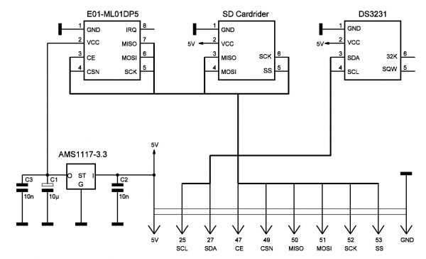
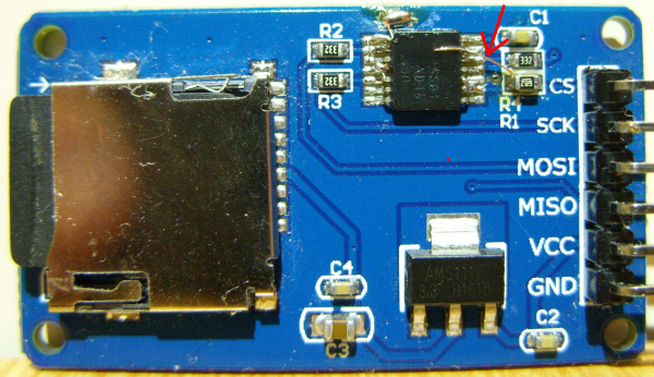 between the output of the input (9) 74LVS125A device selection CS and the matching resistor. Now if there is no access to the memory card, the MISO buffer is disabled and does not interfere with the operation of another device.Breadboard schematic
 Receiver in operation
 To connect the clock to the DS3231, a software I2C (TWI) bus is used.
Arduino IDE software// IMPORTANT: Adafruit_TFTLCD LIBRARY MUST BE SPECIFICALLY
// CONFIGURED FOR EITHER THE TFT SHIELD OR THE BREAKOUT BOARD.
// SEE RELEVANT COMMENTS IN Adafruit_TFTLCD.h FOR SETUP.
//by Open-Smart Team and Catalex Team
//catalex_inc@163.com
//Store:
//
//Demo Function: Display graphics, characters
//Arduino IDE: 1.6.5
// Board: Arduino UNO R3, Arduino Mega2560,Arduino Leonardo
// Board:OPEN-SMART UNO R3 5V / 3.3V, Arduino UNO R3, Arduino Mega2560
//3.2INCH TFT:
//
//OPEN-SMART UNO R3 5V / 3.3V:
//
#include <Adafruit_GFX.h> // Core graphics library
//#include <Adafruit_TFTLCD.h> // Hardware-specific library
#include <MCUFRIEND_kbv.h>
MCUFRIEND_kbv tft;
#include «SdFat.h» // Use the SdFat library
SdFat SD;
SdFile file;
File myFile;
#define SD_CS_PIN SS
#include <SPI.h> // Подключаем библиотеку для работы с шиной SPI
#include <nRF24L01.h> // Подключаем файл настроек из библиотеки RF24
#include <RF24.h> // Подключаем библиотеку для работы с nRF24L01+
RF24 radio(47, 49);
#include <DS3231.h>
DS3231 rtc(27, 25);
Time t;
uint16_t r = 6000;
uint32_t k = 0;
volatile unsigned long data;
float leb_1;
float leb_2;
float leb_3;
float leb_4;
uint8_t pipe;
int rc = 0;
uint8_t time_sec_prev;
uint8_t time_day_prev;
//***********************************************//
// If you use OPEN-SMART TFT breakout board //
// Reconmmend you to add 5V-3.3V level converting circuit.
// Of course you can use OPEN-SMART UNO Black version with 5V/3.3V power switch,
// you just need switch to 3.3V.
// The control pins for the LCD can be assigned to any digital or
// analog pins…but we’ll use the analog pins as this allows us to
//—————————————-|
// TFT Breakout — Arduino UNO / Mega2560 / OPEN-SMART UNO Black
// GND — GND
// 3V3 — 3.3V
// CS — A3
// RS — A2
// WR — A1
// RD — A0
// RST — RESET
// LED — GND
// DB0 — 8
// DB1 — 9
// DB2 — 10
// DB3 — 11
// DB4 — 4
// DB5 — 13
// DB6 — 6
// DB7 — 7
// Assign human-readable names to some common 16-bit color values:
#define BLACK 0x0000
#define BLUE 0x001F
#define RED 0xF800
#define GREEN 0x07E0
#define CYAN 0x07FF
#define MAGENTA 0xF81F
#define YELLOW 0xFFE0
#define WHITE 0xFFFF
#define GRAY 0x8C51
#define GRAYD 0x39E7
//Adafruit_TFTLCD tft(LCD_CS, LCD_CD, LCD_WR, LCD_RD, LCD_RESET);
// If using the shield, all control and data lines are fixed, and
// a simpler declaration can optionally be used:
// Adafruit_TFTLCD tft;
uint16_t g_identifier;
String dataString;
//String numfileMonth =«1.txt»;
char perv [] = {"2.txt"};
//String *numfileMonth=«1.txt» (sizeof (numfileMonth));
///////////////////////////////////////////////////////////////////
void setup(void) {
rtc.begin();
// Для установки времени- раскомментировать нужные строки
// rtc.setDOW(6); // День недели
// rtc.setTime(22, 04, 0); // Время, в формате 24 часа.
// rtc.setDate(4, 5, 2019); // Дата, 29 октября 2018г.
Serial.begin(2000000);
//////// Инициализация экрана
tft.begin(0x65);
tft.reset();
tft.setRotation(0);
tft.cp437(true);
//////////////////Вывод имен, принадлежности оборудования, название организации
tft.fillScreen(BLACK);
tft.setTextColor(WHITE);
tft.setTextSize(2);
tft.setCursor (8, 0);
tft.println ("DEVELOPERS & BUILD");
tft.setCursor (30, 20);
tft.print (utf8rus("Designer V.V."));
tft.setCursor (40, 40);
tft.print (utf8rus("Turner I.I."));
delay (2000);
radio.begin(); // Initialize nRF24L01+ operation
radio.setChannel(120); // Specify reception channel (from 0 to 127)
radio.setDataRate (RF24_250KBPS); // Specify transmission speed (RF24_250KBPS, RF24_1MBPS, RF24_2MBPS), RF24_1MBPS - 1Mbit/sec
radio.setPALevel (RF24_PA_MAX); // Specify transmitter power (RF24_PA_MIN=-18dBm, RF24_PA_LOW=-12dBm, RF24_PA_HIGH=-6dBm, RF24_PA_MAX=0dBm)
radio.openReadingPipe (1, 0xAABBCCDD11LL); // Open pipe 1 with transmitter identifier 0xAABBCCDD11 for receiving data
// Открываем 2 трубу с идентификатором 2 передатчика 0xAABBCCDD22, для приема данных
radio.startListening (); // Turn on the receiver, start listening to open pipes
// radio.stopListening ();
////////Вывод служебной информации
tft.fillScreen(BLACK);
tft.setCursor (8, 0);
tft.setTextSize(1);
////////Начало инициализации SD карты
Serial.println("Initial SD card");
tft.println("Initial SD card");
tft.setCursor (8, 10);
////////Инициализация карты
if (!SD.begin(SD_CS_PIN)) {
Serial.println("initial failed!");
tft.fillRect ( 8, 10, 85, 7, RED);
tft.setTextColor(BLACK);
tft.println("Initial failed!");
return;
}
tft.setTextColor(WHITE);
Serial.println("initialization done");
tft.println("Initialization done");
delay (2000);
////////Считывание времени- даты и присвоение их переменным
t = rtc.getTime();
time_sec_prev = t.sec;
time_day_prev = t.date;
////////Вывод даты принудительно, что б не ждать смены даты для индикации
tft.setCursor ( 180, 0 ); // set cursor position
tft.fillRect ( 178, 0, 65, 7, GRAY); // clear time output area
tft.setTextSize(1);
tft.print(rtc.getDateStr());
////////Вывод названия объектов контроля
tft.setTextSize(2);
tft.setCursor (60, 25);
tft.println (utf8rus("Winches I"));
////////Создание файла лога и вывод результата попытки создания
tft.setTextSize(1);
tft.setCursor(130, 10); // If the log file 2.txt is created, recording will continue in the file
if (SD.exists (perv)) {
//tft.setCursor(0, 90);
tft.println(perv);
Serial.println(perv);
} else {
myFile = SD.open(perv, FILE_WRITE); // If file 2.txt does not exist, it will be created
myFile.close();
tft.println(perv);
Serial.println(perv);
}
}
void loop(void) {
////////Проверка существования запроса вывода лога в монитор СОМ- порта
if (Serial.available() > 0) {
if (1 == Serial.read());
////////И если принята «1»- то вывод
File myFile = SD.open(perv);
// if the file is available, write to it:
if (myFile) {
while (myFile.available()) {
Serial.write(myFile.read());
}
myFile.close();
}
else {
Serial.println("error opening .txt");
}
}
////////Считывание времени
t = rtc.getTime();
tft.setTextColor(WHITE);
////////Если время изменилось, то вывод новых показаний часов
if ( time_sec_prev != t.sec) {
tft.setCursor ( 120, 0 ); // set cursor position
tft.fillRect ( 118, 0, 50, 7, GRAY); // clear time output area
tft.setTextSize(1);
tft.print(rtc.getTimeStr()); // output clock readings
time_sec_prev = t.sec;
}
////////Если дата изменилась, то вывод новой даты
if ( time_day_prev != t.date) {
tft.setCursor ( 180, 0 ); // set cursor position
tft.fillRect (178, 0, 65, 7, GRAY); // clearing the date output area
tft.setTextSize(1);
tft.print(rtc.getDateStr()); // displaying the date readings
time_day_prev = t.date;
}
////////Если доступен радиоприём, то
if (radio.available(&pipe)) {
////////проверка заполнения буфера приёма,
radio.read(&data, sizeof(data));
////////если доступен нужный адрес передатчика, то
if (pipe == 1) {
////////ждём синхронизирующую последовательность нулей для определения
//начала блока данных
if (data == 0000) {
rc = 0;
} else {
rc ++;
}
////////Запись значений счётчиков и расчёт их в 10 и 100-х долях часа
if (rc == 1) {
leb_1 = data / 3600.0;
}
if (rc == 2) {
leb_2 = data / 3600.0;
}
if (rc == 3) {
leb_3 = data / 3600.0;
}
if (rc == 4) {
leb_4 = data / 3600.0;
}
}
}
r ++;
k ++; // just a counter
//////// С определённой условием периодичностью обновление данных
if (r >= 6500) {
tft.setTextSize(2);
tft.fillRect (0, 41, 180, 64, GRAYD);
Serial.println ("Lebedki I");
tft.setCursor (0, 41);
tft.println (leb_1);
Serial.println (leb_1);
tft.println (leb_2);
Serial.println (leb_2);
tft.println (leb_3);
Serial.println (leb_3);
tft.println (leb_4);
Serial.println (leb_4);
Serial.println (k);
r = 0;
}
////////Запись данных в лог на SD каждые 10 мин.
if ((t.min % 10 == 0) && (t.sec == 0)) {
tft.setTextSize(1);
tft.setCursor(200, 10);
tft.setTextColor(BLACK);
////////Создание строки в формате .csv
String dataString = String (rtc.getDateStr()) + ", " + (rtc.getTimeStr()) + ", " + (leb_1) + ", " + (leb_2)
+ ", " + (leb_3) + ", " + (leb_4) + ", ";
////////Запись в файл и вывод результатов процесса записи
myFile = SD.open(perv, FILE_WRITE); // if the file named "2.txt" doesn't exist, it will be created.
if (myFile) {
myFile.println(dataString);
myFile.close();
tft.fillRect (198, 8, 42, 10, GREEN);
tft.println("SD OK");
Serial.println("SD OK");
delay (900); // delay, otherwise it records 13 identical readings until a second passes
} else {
tft.fillRect (198, 8, 42, 10, RED);
tft.println("SD ERR");
Serial.println("SD ERR");
}
}
}Character encoding conversion program/* Recode russian fonts from UTF-8 to Windows-1251 */
String utf8rus(String source)
{
int i,k;
String target;
unsigned char n;
char m[2] = { '0', ' ' };
k = source.length(); i = 0;
while (i < k) {
n = source[i]; i++;
if (n >= 0xC0) {
switch (n) {
case 0xD0: {
n = source[i]; i++;
if (n == 0x81) { n = 0xA8; break; }
if (n >= 0x90 && n <= 0xBF) n = n + 0x30; //0x2F
break;
}
case 0xD1: {
n = source[i]; i++;
if (n == 0x91) { n = 0xB8; break; }
if (n >= 0x80 && n <= 0x8F) n = n + 0x70; //0x6F
break;
}
}
}
m[0] = n; target = target + String(m);
}
return target;
} The character encoding conversion program for displaying Cyrillic characters using Adafruit_GFX library is placed in the same folder as the main program. Also, the glcdfont.c file needs to be replaced with a different font. Library with the required replacement. More on Russian localization can be easily found on the internet.
In summary, I would say that the system has met expectations, it has become easier to track the equipment's operating time. Even though everything is assembled on prototype boards, there have been no urgent complaints about its operation. The first elements have been working for over six months and have survived the winter. for 9 monitored units has been operating since March 5, and the operating time is already officially recorded.
Source: habr.com
