

we discussed how buses and protocols operate in industrial automation. This time, we will focus on modern working solutions: let's look at which protocols are used in systems around the world. We will examine technologies from German companies Beckhoff and Siemens, Austrian B&R, American Rockwell Automation, and Russian Fastwel. We will also explore universal solutions that are not tied to specific manufacturers, such as EtherCAT and CAN.
At the end of the article, there will be a comparison table with the characteristics of the EtherCAT, POWERLINK, PROFINET, EtherNet/IP, and ModbusTCP protocols.
We did not include the PRP, HSR, OPC UA protocols and others in the review, as there are already excellent articles by our engineering colleagues on Habr that deal with the development of automation systems. For example, and .
To start, let's define the terminology: Industrial Ethernet = industrial network, Fieldbus = field bus. In Russian industrial automation, there is often confusion in the terminology regarding the field bus and the lower-level industrial network. These terms are often combined into a vague single concept known as the “lower level,” which is referred to as both a field bus and a lower-level bus, although it may not be a bus at all.
Why is that?This confusion is likely due to the fact that in many modern controllers, the connection of input/output modules is often realized using a backplane or physical bus. This means that some bus contacts and connectors are used to combine several modules into a single node. However, these nodes can, in turn, be connected to each other via either an industrial network or a field bus. In Western terminology, there is a clear distinction: a network is a network, and a bus is a bus. The first is denoted by the term Industrial Ethernet, the second by Fieldbus. In this article, these concepts are suggested to use the terms 'industrial network' and 'field bus' respectively.
The EtherCAT industrial network standard, developed by Beckhoff
The EtherCAT protocol and industrial network is arguably one of the fastest data transmission methods currently available in automation systems. EtherCAT is successfully used in distributed automation systems where the interacting nodes are spread over a large distance.
The EtherCAT protocol uses standard Ethernet frames for transmitting its telegrams, ensuring compatibility with any standard Ethernet equipment, and in essence, data reception and transmission can be organized on any Ethernet controller with the appropriate software.
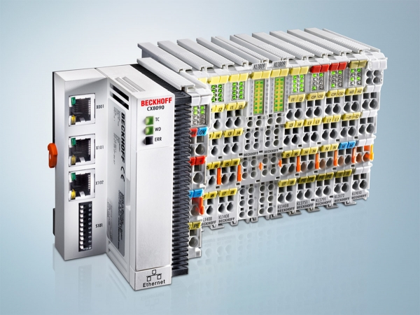
Beckhoff controller with a set of input-output modules. Source:
The protocol specification is open and available, but only within the framework of the development association — EtherCAT Technology Group.
Here's how EtherCAT works (the spectacle is mesmerizing, like playing Zuma Inca):
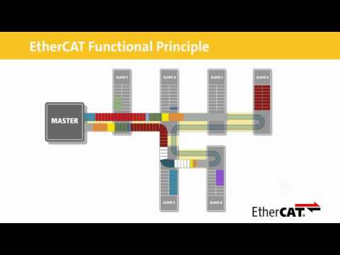
The high speed of communication in this protocol — measured in microseconds — is achieved by the developers abandoning the exchange of telegrams sent directly to specific devices. Instead, a single telegram addressed to all devices simultaneously is sent into the EtherCAT network, where each subordinate information gathering and transmission node (often called a field device) retrieves the data intended for it 'on the fly' and inserts data it is ready to exchange into the telegram. This telegram is then sent to the next subordinate node, where the same operation occurs. After passing through all field devices, the telegram returns to the main controller, which implements the control logic based on the data received from the subordinate devices, again interacting via telegrams with subordinate nodes that issue control signals to the equipment.
The EtherCAT network can have any topology, but it will always function as a ring — due to the use of full-duplex mode and two Ethernet connectors. Thus, the telegram will always be transmitted sequentially to each device on the bus.
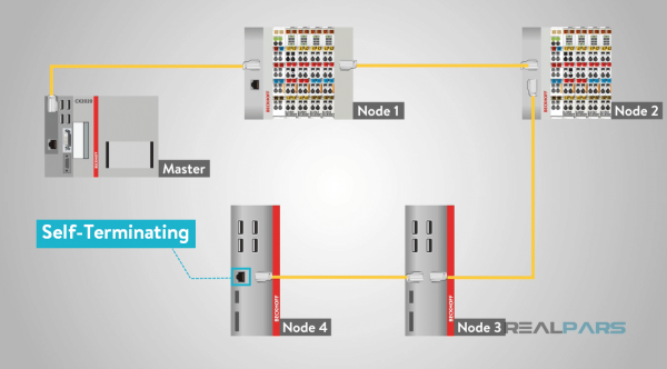
Schematic representation of the EtherCAT network with multiple nodes. Source:
Incidentally, the EtherCAT specification does not impose restrictions on the physical layer 100Base-TX, so the protocol can be implemented based on gigabit and optical lines.
Open industrial networks and the PROFIBUS/NAT standards from Siemens
The German company Siemens has long been known for its programmable logic controllers (PLCs), which are used worldwide.
Data exchange between nodes in an automated system controlled by Siemens equipment is implemented both via the fieldbus called PROFIBUS and through the industrial network PROFINET.
The PROFIBUS bus uses a special two-wire cable with DB-9 connectors. Siemens's version is purple, but we have encountered others in practice :). To connect multiple nodes, the connector can join two cables. There is also a switch for the terminal resistor. The terminal resistor must be enabled on the end devices of the network to indicate that this is the first or last device, and after it, there is nothing but darkness and emptiness (all rs485 work this way). If the resistor is enabled on an intermediate connector, the following section will be disconnected.
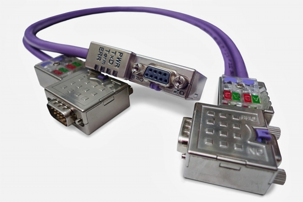
PROFIBUS cable with connectors. Source:
In the PROFINET network, a twisted pair equivalent is used, usually with RJ-45 connectors, and the cable is colored green. If the PROFIBUS topology is a bus, then the topology of the PROFINET network can be anything: a ring, a star, a tree, or all of these combined.
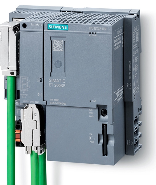
Siemens controller with connected PROFINET cable. Source: w3.siemens.com
There are several bus communication protocols for PROFIBUS and the PROFINET network.
For PROFIBUS:
- PROFIBUS DP — this protocol implementation implies communication with remote subordinate devices; for PROFINET, the corresponding protocol is PROFINET IO.
- PROFIBUS PA — is essentially the same as PROFIBUS DP, but is used for explosion-proof data transmission and power supply (analog of PROFIBUS DP with different physical properties). There is currently no explosion-proof protocol analogous to PROFIBUS for PROFINET.
- PROFIBUS FMS — is intended for data exchange with systems from other manufacturers that cannot use PROFIBUS DP. The PROFINET equivalent of PROFIBUS FMS is the PROFINET CBA protocol.
For PROFINET:
- PROFINET IO;
- PROFINET CBA.
The PROFINET IO protocol is divided into several classes:
- PROFINET NRT (non-real-time) is used in applications where timing parameters are not critical. It employs the Ethernet TCP/IP data transfer protocol, as well as UDP/IP.
- PROFINET RT (real-time) implements input/output data exchange using Ethernet frames, while diagnostic and communication data are still transmitted via UDP/IP.
- PROFINET IRT (isochronous real-time) was specifically developed for motion control applications and includes an isochronous phase of data transmission.
Regarding the implementation of the hard real-time protocol PROFINET IRT, two communication channels are distinguished for interactions with remote devices: isochronous and asynchronous. The isochronous channel, with a fixed cycle length, utilizes clock synchronization and transmits time-critical data using Level 2 telegrams. The transmission duration in the isochronous channel does not exceed 1 millisecond.
In the asynchronous channel, so-called real-time data is transmitted, which is also addressed via MAC address. Additionally, various diagnostic and auxiliary information is sent over TCP/IP. Neither real-time data nor any other information can, of course, interrupt the isochronous cycle.
The extended functionality set of PROFINET IO is not required for every industrial automation system, so this protocol is scaled for specific projects, considering conformance or application classes: CC-A, CC-B, CC-C. Conformance classes allow the selection of field devices and bus components with the minimum necessary functionality.
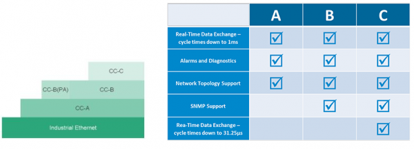
Source:
The second exchange protocol in the PROFINET network — PROFINET CBA — facilitates industrial communication between equipment from various manufacturers. The main production unit in CBA systems is an entity known as a component. This component typically represents a combination of the mechanical, electrical, and electronic parts of a device or installation, as well as the corresponding application software. For each component, a program module is selected that contains a complete description of the interface of this component according to the requirements of the PROFINET standard. These program modules are then used for data exchange with devices.
Ethernet POWERLINK Protocol by B&R
The Powerlink protocol was developed by the Austrian company B&R in the early 2000s. It is yet another implementation of a real-time protocol over the Ethernet standard. The protocol specification is available and freely distributed.
In the Powerlink technology, a mechanism known as mixed polling is used, where all interactions between devices are divided into several phases. Critically important data is transmitted in the isochronous exchange phase, for which the required response time is configured; the remaining data will be transmitted as possible in the asynchronous phase.
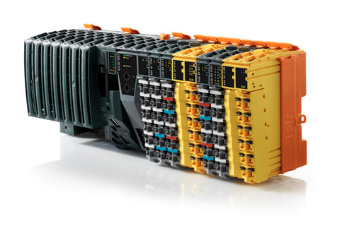
B&R Controller with a set of input/output modules. Source: br-automation.com
Initially, the protocol was implemented over the physical layer 100Base-TX, but later a gigabit implementation was developed.
The Powerlink protocol uses a scheduling mechanism for data exchange. A token or control message is sent over the network, which determines which device currently has permission to exchange data. At any given time, only one device may have access to the exchange.
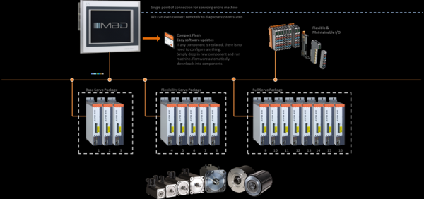
Schematic representation of an Ethernet POWERLINK network with several nodes.
In the isochronous phase, the polling controller sequentially sends a request to each node from which critical data needs to be obtained.
The isochronous phase is carried out, as mentioned, with a customizable cycle time. In the asynchronous phase of communication, the IP protocol stack is used, and the controller requests non-critical data from all nodes, which respond as they gain access to transmit over the network. The time ratio between the isochronous and asynchronous phases can be adjusted manually.
Ethernet/IP protocol by Rockwell Automation
The EtherNet/IP protocol was developed with the active participation of the American company Rockwell Automation in 2000. It uses the TCP and UDP IP stack and extends it for use in industrial automation. Contrary to popular belief, the second part of the name does not mean Internet Protocol, but rather Industrial Protocol. UDP IP uses the communication stack of the CIP (Common Interface Protocol), which is also utilized in ControlNet/DeviceNet networks and is implemented over TCP/IP.
The EtherNet/IP specification is publicly available and distributed for free. The topology of the Ethernet/IP network can be arbitrary and may include a ring, star, tree, or bus.
In addition to the standard functions of HTTP, FTP, and SMTP protocols, EtherNet/IP implements the transfer of time-critical data between the polling controller and I/O devices. Non-time-critical data is transmitted using TCP packets, while time-critical delivery of cyclical control data takes place over the UDP protocol.
To synchronize time in distributed systems, EtherNet/IP uses the CIPsync protocol, which is an extension of the CIP communication protocol.
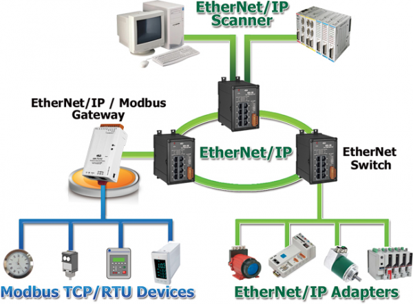
Schematic representation of an Ethernet/IP network with multiple nodes and Modbus device connections. Source:
To simplify the configuration of the EtherNet/IP network, most standard automation devices come with predefined configuration files.
Implementation of the FBUS protocol at Fastwel
We debated for a long time about whether to include the Russian company Fastwel with its domestic implementation of the industrial protocol FBUS in this list, but ultimately decided to write a couple of paragraphs for a better understanding of the realities of import substitution.
There are two physical implementations of FBUS. One is a bus where the FBUS protocol operates over the RS485 standard. Additionally, there is an FBUS implementation in the industrial Ethernet network.
FBUS is difficult to call a high-speed protocol; the response time strongly depends on the number of input-output modules on the bus and the exchange parameters, usually fluctuating between 0.5 to 10 milliseconds. One subordinate FBUS node can contain only 64 input-output modules. For the field bus, the cable length cannot exceed 1 meter, which means distributed systems are not feasible. More precisely, they can be considered, but only when using the industrial FBUS network over TCP/IP, which results in a several-fold increase in polling time. Bus extenders can be used to connect modules, allowing for convenient positioning of modules in the automation cabinet.
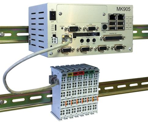
Fastwel controller with connected input-output modules. Source:
In summary: how all this is used in industrial automation systems (АСУ ТП)
Naturally, the variety of modern industrial data transmission protocols is much greater than what we have described in this article. Some are tied to specific manufacturers, while others are more universal. When developing automated process control systems (АСУ ТП), engineers choose optimal protocols considering specific tasks and constraints (technical and budgetary).
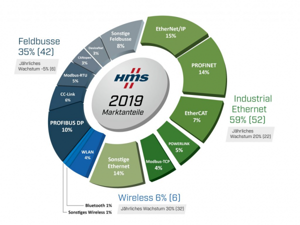
Speaking of the prevalence of a particular communication protocol, one can refer to a diagram from the company HMS Networks AB, which illustrates the market shares of various communication technologies in industrial networks.
Source:
As seen in the diagram, PRONET and PROFIBUS from Siemens hold leading positions.
Interestingly, 6 years ago .
The table below summarizes the data for the described communication protocols. Some parameters, such as performance, are expressed in abstract terms: high/low. Numerical equivalents can be found in performance analysis articles.
| EtherCAT | POWERLINK | PROFINET | EtherNet/IP | ModbusTCP |
Physical Layer | 100/1000 BASE-TX | 100/1000 BASE-TX | 100/1000 BASE-TX | 100/1000 BASE-TX | 100/1000 BASE-TX |
Data transmission rate | Link level (Ethernet frames) | Link level (Ethernet frames) | Link level (Ethernet frames), Network/Transport (TCP/IP) | Network/Transport (TCP/IP) | Network/Transport (TCP/IP) |
Real-time support | Yes | Yes | Yes | Yes | No |
Performance | High | High | IRT – high, RT – medium | Average | Low |
Cable length between nodes | 100m | 100m/2km | 100m | 100m | 100m |
Transmission phases | No | Isochronous + asynchronous | IRT – isochronous + asynchronous, RT – asynchronous | No | No |
Number of nodes | 65535 | 240 | TCP/IP network limitation | TCP/IP network limitation | TCP/IP network limitation |
Collision resolution | Ring topology | Clock synchronization, transmission phases | Ring topology, transmission phases | Switches, star topology | Switches, star topology |
Hot swapping | No | Yes | Yes | Yes | Depending on the implementation |
Cost of equipment | Low | Low | High | Average | Low |
The application areas of the described exchange protocols, field buses, and industrial networks are very diverse. Ranging from chemical and automotive industries to aerospace technologies and electronics manufacturing. High-speed exchange protocols are in demand in real-time positioning systems of various devices and in robotics.
What protocols have you worked with and where have you applied them? Share your experiences in the comments. 🙂
Source: habr.com
