

"One Day in the Life of a Squirrel" or from Process Modeling to Designing the Automated Inventory System "Squirrel-1.0" (Part 1)
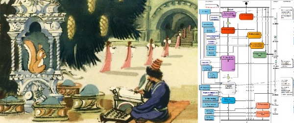
What does 'squirrel' have to do with it?
Let me explain what 'squirrel' has to do with it. Coming across amusing projects for studying UML based on themes from fairy tales (for example, [1]), I decided to prepare a similar example for my students so they could start by studying just three types of diagrams: Activity Diagram, Use-case Diagram, and Class Diagram. I intentionally do not translate the names of the diagrams into Russian to avoid disputes over the "difficulties of translation." I will clarify their purposes a bit later. In this example, I use the Enterprise Architect environment from the Australian company [2] – a good tool for reasonable money. During class, I also use [3], a decent free object-oriented design tool that supports UML2.0 and BPMN standards, without excessive embellishments in terms of graphical capabilities, but sufficiently adequate for learning the basics of the language.
We intend to automate the process of accounting for material assets that arises in these processes.
…
An island lies on the sea, (E1, E2)
A city stands on the island (E3, E1)
With golden-domed churches, (E4)
With towers and gardens; (E5, E6)
A fir tree grows in front of the palace, (E7, E8)
And under it, a crystal house; (E9)
A squirrel lives there, (A1)
And what a clever one! (A1)
The squirrel sings songs, (P1, A1)
And gnaws on nuts, (P2)
And the nuts are not ordinary, (C1)
All with golden shells, (C2)
The kernels are pure emerald; (C3)
The servants guard the squirrel, (P3, A2)
They serve her with various attendants (P4)
And a strict clerk is assigned (A3)
A strict account must be kept of the nuts; (P5, C1)
The troops pay her honors; (P6, A4)
From the shells, they forge coins, (P7, C2, C4)
And send them out across the world; (P8)
The girls sprinkle emeralds (P9, A5, C3)
Into the storerooms, and under the silt; (E10, E11)
…
(A.S. Pushkin's "The Tale of Tsar Saltan, about his glorious and mighty son Prince Guidon Saltanovich and the beautiful Swan Princess") — 10 years from concept to publication, by the way!)
A little about the codes written to the right of the lines. “A” (from “Actor”) indicates that the line contains information about a participant in the process. “C” (from “Class”) indicates information about class objects processed during the execution of processes. “E” (from “Environment”) represents information about class objects that characterize the execution environment of processes. “P” (from “Process”) refers to the processes themselves.
By the way, the precise definition of a process also claims to be the source of methodological disputes, if only because there are different types of processes: business, production, technological, etc. (for example, you can get acquainted with [4] and [5]). To avoid controversy, let’s agree that we are interested in the process from the perspective of its repeatability over time and the need for automation , i.e., transferring the execution of any part of the operations of the process to an automated system. Notes on the application of the Activity diagramLet’s start modeling our process and use the Activity diagram for this. First, I will explain how the codes mentioned above will be used in the model. It is easier to explain with a graphical example, and we'll also review some (almost all of the necessary) elements of the Activity diagram.
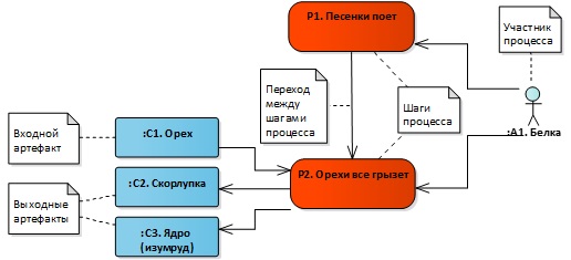
Let’s analyze the following fragment:
We have two steps of the process P1 and P2, participant A1, and objects of three different classes: an object of class C1 enters the step, while objects of classes C2 and C3 are obtained at the output, as a result of this step P2 of our process. We will use the following modeling elements for the diagram.
The fragment of our process can be represented roughly like this (Figure 1).
…
The squirrel sings songs, (P1, A1)
And gnaws on nuts, (P2)
And the nuts are not ordinary, (C1)
All with golden shells, (C2)
The kernels are pure emerald; (C3)
…
Figure 1. Fragment of the Activity diagram
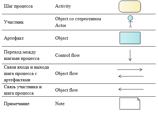
To organize the space and structure the Activity diagram, we will apply a somewhat non-standard approach, from the perspective of the classical use of UML notation. But there are several reasons for this. Firstly, just before modeling, we will create what is called a
modeling agreement
To organize the space and structure the Activity diagram, we will apply a somewhat unconventional approach compared to the classic use of UML notation. There are several reasons for this. Firstly, before we begin modeling, we will create what is known as a modeling agreement, in which we will capture all the features of notation usage. Secondly, this approach has been successfully applied multiple times at the stage of business modeling in real projects to create software systems, and the results have been documented by our small author group in the corresponding copyright object [6], as well as utilized in a textbook [7]. For the Activity diagram, we will define that the diagram's field is structured using swim lanes. The name of the lane will correspond to the type of elements on the diagram that will be placed in that lane.
‘Input and Output Artifacts’: this lane will host Objects—items that are used or result from a certain step in the process.
‘Process Steps’: here we will place Activity elements—actions of process participants.
‘Participants’: a lane for elements that will denote the roles of action performers in our process; for them, we will use the same modeling element Object—but we will add the stereotype ‘Actor’.
The next lane is called ‘Business Rules’ and this lane will contain the textual representation of the rules for step execution, using the modeling element Note.
We will pause here, although it could also be useful to utilize a lane ‘Tools’ to gather information about the level of process automation. Another lane might be useful ‘Positions and Departments of Participants’, which can be used to link roles with the positions and departments of process participants.
Everything I just described is a fragment of the modeling agreement, this part of the agreement pertains to the rules for organizing a diagram and, accordingly, the rules for its writing and reading.
‘Recipe’
Now let’s consider the modeling option of the system precisely from the Activity diagram. This is just one of the options; I will note that it is certainly not the only one. The Activity diagram will interest us in terms of its role in transitioning from process modeling to the design of an automated system. To do this, we will follow the methodological recommendations — a kind of recipe consisting of only five stages and involving the development of three types of diagrams. Applying this recipe will help obtain a formalized description of the process we want to automate and gather data for system design. For students beginning their study of UML, this serves as a lifebuoy that prevents drowning in the diversity of visual tools and techniques available in UML and modern modeling tools.
Here, in fact, is the recipe itself, followed by the diagrams constructed for our 'fairy-tale' subject area.
Stage 1. We describe the process in the form of an Activity diagram. For processes with more than 10 steps, it makes sense to apply the principle of decomposing process steps to improve the readability of the diagram.
Stage 2. Identify what can be automated. (steps can be highlighted on the diagram, for example).
Stage 3. The step to be automated needs to correspond to one or more functions of the system. (the relationship can be many-to-many), we draw a Use-case diagram. These are the functions of our system.
Stage 4. We will describe the internal organization of the automated system using a Class diagram. – Class. The swimlane 'Input and Output Objects (Documents)' on the Activity diagram forms the basis for building the object model and the entity-relationship model.
Stage 5. We will analyze the notes on the 'Business Rules' lane., which impose various kinds of constraints and conditions, gradually transforming into non-functional requirements.
The resulting set of diagrams (Activity, Use-case, Class) gives us a formalized description in a sufficiently strict notation, i.e., it has an unambiguous reading. Now we can develop the technical specification, clarify the requirements specification, etc.
Let's start modeling.
Stage 1. We describe the process in the form of an Activity diagram.
I would like to remind you that we structured the chart area using 'swimlanes', with elements of the same type placed in each lane (Figure 2). In addition to the elements described above, we will use additional elements, let's describe them.
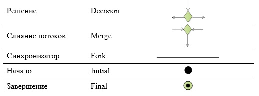
The Decision point on the diagram represents the branching point of our process, while the Merge point is where the flows reconnect. The transition conditions are written in square brackets.
We will show parallel branches of the process between two Fork synchronizers.
Our process can have only one beginning – one entry point (Initial). However, there can be multiple endings (Final), although not for our specific diagram.
With numerous arrows, especially when there are many elements and connections, it can be useful to first highlight the stages of the process and then perform a decomposition of those stages. However, I would like to represent our 'fairy tale' process entirely on one diagram, ensuring that the arrows do not 'stick together', allowing us to accurately trace what is related to what.
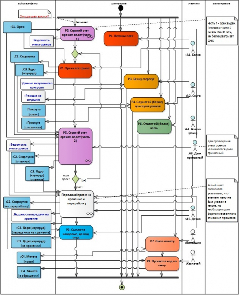
Figure 2. Activity Diagram – overall view of the process
Since some details of the process are omitted in the poetic lines, they had to be restored; these are shown with elements featuring a white background. These details include the step 'Transfer/Reception for storage and processing' and several input and output artifacts. It is worth noting that this step does not fully reveal the process, as we would need to separately indicate the transfer step and the reception step, and also add a separate step for the shells, plus consider that all these material valuables must be temporarily stored somewhere, etc.
We also note that the question regarding the origin of the nuts remains unanswered – where they come from and how they reach the squirrel. This question (highlighted in red font in a note element) requires further elaboration! This is how an analyst works – collecting information bit by bit, making assumptions and receiving 'okay' or 'not okay' from subject matter experts – very important and simply irreplaceable people during the business modeling stage in system creation.
We also note that the process step P5 consists of two parts.
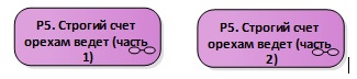
We will decompose each part and examine it in detail (Figure 3, Figure 4), as the activities performed within these steps will be automated.
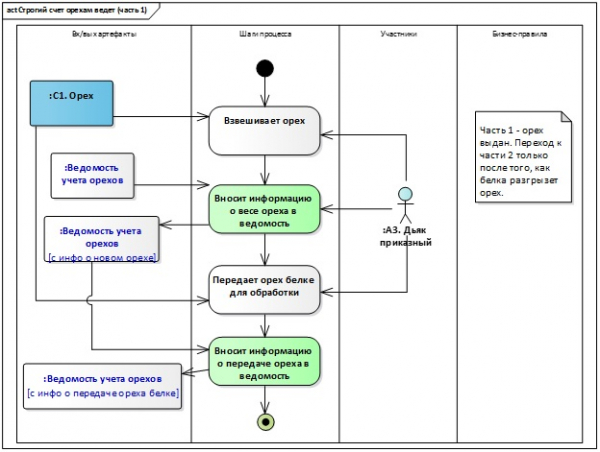
Figure 3. Activity Diagram – Breakdown (Part 1)
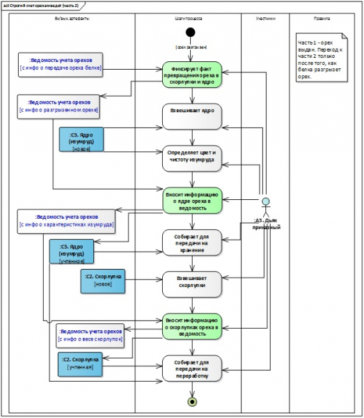
Figure 4. Activity Diagram – Breakdown (Part 2)
Stage 2. Identify what can be automated.
The steps to be automated in the diagrams are highlighted in color (see Figure 3, Figure 4).

All tasks are performed by a single participant in the process – the Deacon Commander:
- Enters the information about the weight of the nut into the ledger;
- Enters the information about the transfer of the nut into the ledger;
- Records the fact of transforming the nut into shells and kernel;
- Enters the information about the kernel of the nut into the ledger;
- Enters the information about the shells of the nut into the ledger.
Analysis of the completed work. What's next?
Thus, we have done significant preparatory work: gathered information about the process we are going to automate; started forming an agreement on modeling (currently only regarding the use of the Activity diagram); carried out process modeling and even performed decomposition of several of its steps; identified the steps of the process that we will automate. Now we are ready to move on to the next stages and begin designing the functions of the system and its internal organization.
As is well known, theory without practice is nothing. It is essential to try "modeling" hands-on; it is beneficial for understanding the proposed approach. For example, one can work in a modeling environment. [3]. We have only decomposed part of the steps of the overall process diagram (see Figure 2). As a practical task, you could be asked to replicate all diagrams in the Modelio environment and perform the decomposition of the step "Transfer/accept for storage and processing."
We are not considering work in specific modeling environments yet, but this could be the subject of independent articles and reviews.
In the second part of the article, we will discuss modeling and design techniques necessary for stages 3-5, using UML Use-case and Class diagrams. Continuation follows.
List of sources
- Website "UML2.ru". Community Analysts Forum. General Section. Examples. Examples of fairy tales formatted as UML diagrams. [Electronic resource] Access mode: Internet:
- Sparx Systems website. [Electronic resource] Access mode: Internet:
- Modelio website. [Electronic resource] Access mode: Internet:
- Great Encyclopedia Dictionary. Process (interpretation). [Electronic resource] Access mode: Internet:
- Website 'Organization of Effective Management'. Blog. Section 'Business Process Management'. Definition of a business process. [Electronic resource] Access mode: Internet:
- Certificate No. 18249 of registration and deposit of the result of intellectual activity. Alfimov R.V., Zolotukhina E.B., Krasnikova S.A. Manuscript of the educational and methodological guide titled 'Modeling the Subject Area Using Enterprise Architect' // 2011.
- Zolotukhina E.B., Vishnya A.S., Krasnikova S.A. Modeling Business Processes. — M.: KURS, NITS INFRA-M, EBS Znanium.com. — 2017.
Source: habr.com
