

"A Day in the Life of a Squirrel" or From Modeling Processes to Designing an Automated System for Inventory Accounting "Belka-1.0" (Part 2)
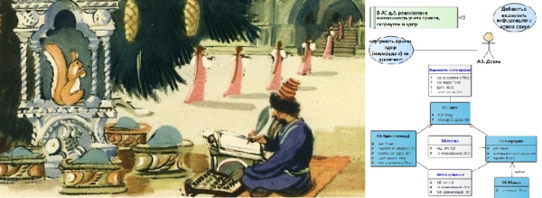
Summary of the previous episode
In We used a "fairy tale" subject area, inspired by examples of studying UML diagrams based on fairy tale plots (see, for example, [1]). Before starting the modeling, we agreed on the use of certain elements of the Activity diagram and began forming an agreement on modeling. Considering these agreements, in the 1st stage, we described the process in the form of Activity diagrams, and in the 2nd stage, we identified the steps of the process that require (and are possible for) automation.
Let me remind you that we plan to automate the inventory accounting activities, which arise in these processes.
…
An island lies on the sea, (E1, E2)
A city stands on the island (E3, E1)
With golden-domed churches, (E4)
With towers and gardens; (E5, E6)
A fir tree grows in front of the palace, (E7, E8)
And under it, a crystal house; (E9)
A squirrel lives there, (A1)
And what a clever one! (A1)
The squirrel sings songs, (P1, A1)
And gnaws on nuts, (P2)
And the nuts are not ordinary, (C1)
All with golden shells, (C2)
The kernels are pure emerald; (C3)
The servants guard the squirrel, (P3, A2)
They serve her with various attendants (P4)
And a strict clerk is assigned (A3)
A strict account must be kept of the nuts; (P5, C1)
The troops pay her honors; (P6, A4)
From the shells, they forge coins, (P7, C2, C4)
And send them out across the world; (P8)
The girls sprinkle emeralds (P9, A5, C3)
Into the storerooms, and under the silt; (E10, E11)
…
(A.S. Pushkin's "Tale of Tsar Saltan, of his glorious and mighty son, the hero Prince Guidon Saltanovich, and of the beautiful Swan Princess", )
In this example, I am using the Enterprise Architect environment from an Australian company. [2], and in my teaching sessions I apply [3].
Let me remind you that there are different types of processes, you can get acquainted with them, for example, we are interested in the process from the perspective of its repeatability over time and the need for automation [5].
For more details on the applied modeling and design approaches, see [6, 7].
Full UML specification can be found. [8].
Now we are ready to move on to the next stages and start designing the functions of the system and its internal organization. The numbering of figures will continue.
Stage 3. The step to be automated needs to correspond to one or more functions of the system.
The automated system (AS) being developed is intended for strict accounting of nuts, remember? For each identified step (see Figure 3, Figure 4 ), which we will automate, we will write a functional requirement using an expression like "The system must provide the ability to ..." and develop a Use-case diagram. We are currently supplementing our modeling agreement with new rules. I will explain which elements we will use.
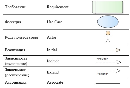
Between the "User Role" and the "Function", we will use the "Association" link (Figure 5), meaning that for a user with this role, it is possible to perform this function.
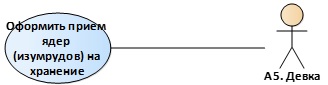
Figure 5. Using an «Association» type relationship
From «Function» to «Requirement», we will establish an «Implementation» relationship (Figure 6) to show that this requirement will be implemented by these functions. The relationship can also be «many-to-many», meaning that one function may participate in the implementation of several requirements, and more than one function may be needed to fulfill a requirement.

Figure 6. Using an «Implementation» type relationship
If one function requires another function to be executed for its own performance, we will use a «Dependency» relationship with the stereotype «Include» — inclusion (Figure 7). However, if the execution of the additional function is required under certain conditions, we will use a «Dependency» relationship with the stereotype «Extend» — extension. It's easy to remember: «Include» is ALWAYS, and «Extend» is SOMETIMES.
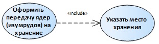
Figure 7. Using an «Include Dependency» type relationship
As a result, our diagram will look approximately like this (Figure 8).
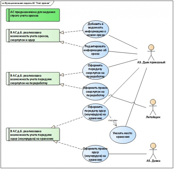
Figure 8. Use-case diagram (functional model of the system)
Additionally, the use-case diagram is used to model user roles (Figure 9).
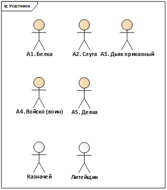
Figure 9. Use-case diagram (user roles of the system)
Stage 4. We will describe the internal organization of the automated system using a Class diagram.
Using information about the input and output artifacts of our process (see Activity diagrams — Figure 2, Figure 3, Figure 4), we will develop a class diagram. We will use modeling elements «Class» and various types of relationships between them.
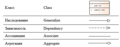
To show the «whole-part» relationship, we will use an «Aggregation» type relationship (Figure 10): a nut is the whole, while the shell and kernel are the parts.
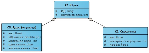
Figure 10. «Whole-Part» relationship
As a result, the fragment of our diagram will look approximately like this (Figure 11). The classes highlighted in color are those we defined directly in the textual description of the process.
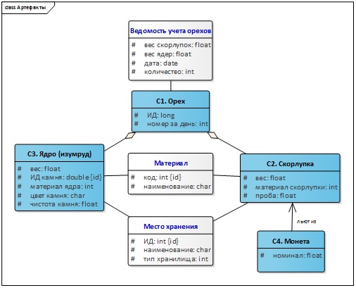
Figure 11. Class diagram
The class diagram was also used to model other artifacts – not just those related to the conceptual model of the automated process of accounting for material assets, but also related to the execution environment – the environment (Figure 12) and the "neighboring" processes (Figure 13), which may influence the automated process but are not currently in our focus (we assume that the system will evolve, and this information will become useful).
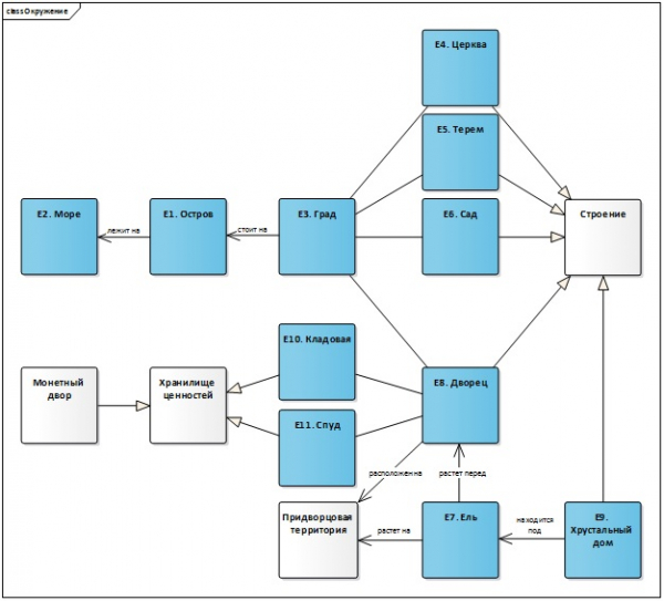
Figure 12. Class Diagram (Environment)
The inheritance relationship shows the generalization of various constructions, with the "child" classes under the generalizing "parent" class "Construction."
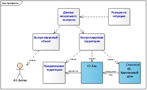
Figure 13. Class Diagram (Additional Information on Artifacts)
"Response to the Situation" depends on "Visual Control Data." For several dependency relationships, the stereotype "trace" is used to indicate the tracing of classes that are not explicitly mentioned in the process description but are necessary for its automation, to the classes for which there is a precise reference in our description.
Stage 5. We will analyze the notes on the 'Business Rules' lane.
The following rules were specified (see Figure 2 ):
- the necessity to split one of the steps into 2 parts, the second part starts to execute only under certain conditions;
- assignment for accounting nuts to a specific official;
- a technical label (white color of elements) indicating that the element was not explicitly mentioned in the process description.
It should be noted that we have already used all these rules in the development of the diagrams.
Final Remarks
So, we went through 5 stages and built 3 types of diagrams. I will add a brief comment about organizing our models in the modeling environment. There are many frameworks that help structure the developed models, but this is not the subject of this article, so we will limit ourselves to the following simple set of packages for organizing our project: Business Process, Functional Model, Artifacts, Participants, and Environment (Figure 14).
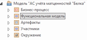
Figure 14. Project Package Structure
Thus, we have developed consistent models that describe the accounting system for material assets from various perspectives: a model of the automatable business process, a functional model, and a model of the internal organization of the system at a conceptual level.
List of sources
- Website "UML2.ru". Community Analysts Forum. General Section. Examples. Examples of fairy tales formatted as UML diagrams. [Electronic resource] Access mode: Internet:
- Sparx Systems website. [Electronic resource] Access mode: Internet:
- Modelio website. [Electronic resource] Access mode: Internet:
- Great Encyclopedia Dictionary. Process (interpretation). [Electronic resource] Access mode: Internet:
- Website 'Organization of Effective Management'. Blog. Section 'Business Process Management'. Definition of a business process. [Electronic resource] Access mode: Internet:
- Certificate No. 18249 of registration and deposit of the result of intellectual activity. Alfimov R.V., Zolotukhina E.B., Krasnikova S.A. Manuscript of the educational and methodological guide titled 'Modeling the Subject Area Using Enterprise Architect' // 2011.
- Zolotukhina E.B., Vishnya A.S., Krasnikova S.A. Modeling Business Processes. — M.: KURS, NITS INFRA-M, EBS Znanium.com. — 2017.
- OMG Unified Modeling Language (OMG UML) Specification. Version 2.5.1. [Electronic resource] Access mode: Internet:
Source: habr.com
