

I see that , the historical part of my narrative was liked by the audience, so it's worth continuing.
High-speed trains, like the TGV, no longer rely solely on pneumatic brakes.
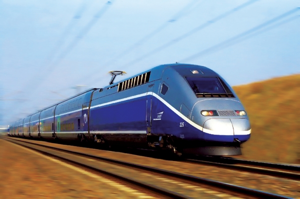
Today we will discuss modernity, specifically the approaches to creating braking systems for rolling stock used in the 21st century, which will soon celebrate its third decade.
1. Classification of Rolling Stock Brakes
Based on the physical principle of generating braking force, all railway brakes can be divided into two main types: frictional, which use the force of friction, and dynamic, which use the traction drive to create braking torque.
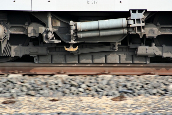
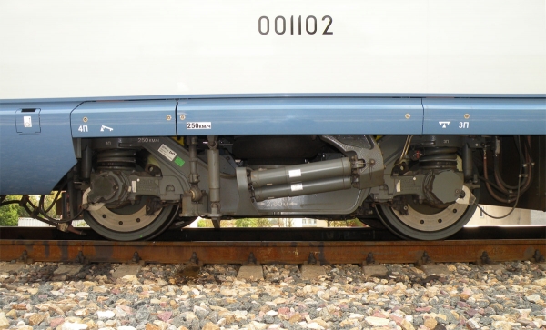
Friction brakes include all types of block brakes, including disc brakes, as well as maglev brakes, which are used in high-speed rail transport, mainly in Western Europe. In the 1520 gauge, this type of brake was applied solely to the ER200 electric train. Regarding the 'Sapsan,' RZhD decided against using maglev brakes on it, although the prototype of this electric train, the German ICE3, is equipped with such brakes.
The ICE3 train's bogie with a maglev brake
The 'Sapsan' train's bogie
Dynamic, or more precisely, electrodynamic brakes include all brakes whose operation is based on switching traction electric motors to generator mode (regenerative and rheostatic brake), as well as braking by back-feed.
With regenerative and rheostatic braking, everything is relatively clear — the engines are converted to generator mode in one way or another, and in the case of regeneration, they supply energy to the contact network, while in the case of rheostat braking, the generated energy is dissipated in special resistors. Both types of brakes are used on trains with locomotive traction as well as in multiple unit trains, where the electrodynamic brake serves as the primary working brake due to the large number of traction electric motors spread throughout the train. The only drawback of electrodynamic braking (EDB) is its inability to bring the train to a complete stop. When the effectiveness of EDB decreases, it is automatically replaced by a pneumatic friction brake.
As for braking by reversing, it allows for a complete stop because it involves reversing the traction motor while in motion. However, this mode is mostly considered an emergency measure — its regular use can damage the traction drive. For example, with a brushed motor, when the polarity of the voltage supplied to it is changed, the counter electromotive force produced in the rotating motor doesn't subtract from the supply voltage but adds to it — the wheels continue to rotate in the same direction as in the traction mode! This leads to a sharp increase in current, and the best-case scenario is that the electrical protection devices will be triggered.
For this reason, all possible measures are taken on locomotives and electric trains to prevent the reversal of motors while in motion. The reversing lever is mechanically locked when the driver's controller is in the operational positions. On the 'Sapsan' and 'Lastochka' trains, turning the reversing switch at speeds above 5 km/h will result in immediate emergency braking.
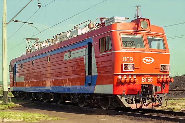
However, some domestic locomotives, such as the VL65 electric locomotive, use reverse braking as a standard mode at low speeds.
Reverse braking is a standard mode provided by the control system on the VL65 electric locomotive.
It must be said that despite the high efficiency of electrodynamic braking, every train is always, I emphasize — always equipped with a pneumatic automatic brake, which activates by releasing air from the brake line. Both in Russia and around the world, the good old block friction brakes stand guard over the safety of movement.
According to their functional purpose, friction brakes are classified into
- Parking, manual or automatic
- Train brakes — pneumatic (PT) or electropneumatic (EPT) brakes installed on each unit of rolling stock in a train and centrally controlled from the driver's cabin.
- Locomotive brakes — pneumatic direct-acting brakes designed for stopping the locomotive without affecting the rest of the train. They are controlled separately from the train brakes.
2. Parking brake
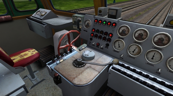
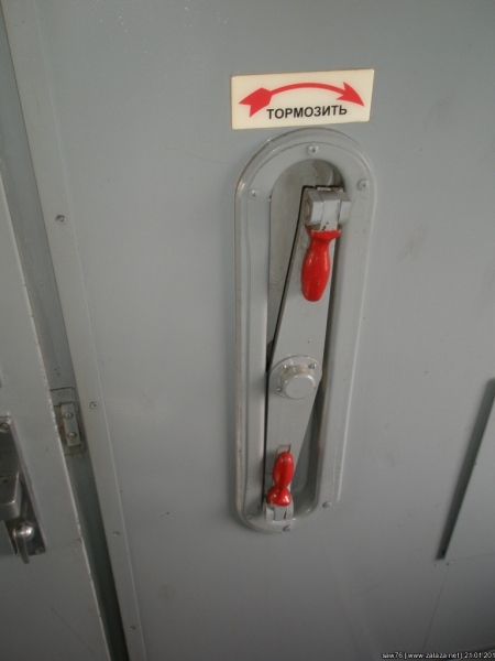
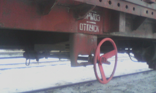
The manual brake with a mechanical drive hasn't disappeared from the rolling stock; it is installed on both locomotives and cars — it simply changed its role and became a parking brake, preventing any unintentional movement of the rolling stock in case of air release from its pneumatic system. The red wheel, reminiscent of a ship's steering wheel, is the drive for the manual brake, one of its execution options.
The manual parking brake wheel in the cabin of the VL60pk electric locomotive.
Manual brake in the passenger car vestibule.
Manual brake on a modern freight car.
The manual brake with a mechanical drive presses the same pads against the wheels that are used in regular braking.
On modern rolling stock, particularly on the EVS1/EVS2 'Sapsan' electric trains, ES1 'Lastochka', and the EP20 electric locomotive, the parking brake is automatic and the pressing of pads to the brake disc is performed by spring energy accumulators.. Part of the clamping mechanisms that press the pads against the brake discs are equipped with powerful springs, so powerful that the release is performed by a pneumatic actuator at a pressure of 0.5 MPa. In this case, the pneumatic actuator counteracts the springs that press the pads. The control of such a parking brake is carried out by buttons on the driver's panel.
Control buttons for the parking spring brake (PSB) on the ES1 'Lastochka' electric train
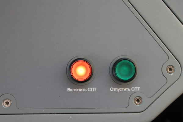
In terms of its design, this brake is similar to those used on powerful trucks. However, as a primary brake in trains, such a system is completely unsuitable, and I will explain why in detail after discussing the operation of train pneumatic brakes.
3. Pneumatic brakes of freight type
Each freight car is equipped with the following set of braking equipment
Braking equipment of the freight car: 1 — brake connection hose; 2 — end valve; 3 — emergency valve; 5 — dust catcher; 6, 7, 9 — air distributor modules no. 483; 8 — cut-off valve; AR — air distributor; TM — brake pipe; ZR — auxiliary reservoir; TC — brake cylinder; AR — freight automatic mode
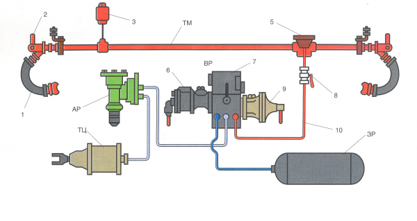
Brake pipe (TM) — a pipe with a diameter of 1.25" running along the entire car, at the ends it is equipped with end valves, for disconnecting the brake pipe when uncoupling the car before separating the flexible connection hoses. The brake pipe normally maintains a charging pressure of 0.50 — 0.54 MPa, so disconnecting the hoses without closing the end valves is a dubious activity that can literally cost you your head.
The reserve air, directly supplied to the brake cylinders, is stored in the reserve reservoir (The auxiliary reservoir), which in most cases has a volume of 78 liters. The pressure in the auxiliary reservoir is exactly equal to the pressure in the brake line. However, it is not 0.50 — 0.54 MPa. The fact is that such pressure will be in the brake line of the locomotive. And the farther from the locomotive, the lower the pressure in the brake line, because there are inevitably leaks causing air to escape. So, the pressure in the brake line of the last car in the train will be somewhat lower than the charged pressure.
Brake cylinder, and on most cars, there is one brake cylinder that, when filled from the auxiliary reservoir, presses all the brake pads available on the car against the wheels through the brake lever transmission. The volume of the brake cylinder is about 8 liters, so at full braking, the pressure in it does not exceed 0.4 MPa. The pressure in the auxiliary reservoir decreases to the same value.
The main "actor" in this system is the air distributor. This device responds to changes in pressure in the brake line, performing a certain operation depending on the direction and rate of change of that pressure.
When the pressure in the brake line decreases, braking occurs. But not with any decrease in pressure — the drop in pressure must occur at a certain rate, known as the service braking rate. This rate is provided by the driver's valve in the locomotive cab and ranges from 0.01 to 0.04 MPa per second. If the pressure decreases at a lower rate, braking does not occur. This is done to ensure that the brakes do not engage during normal leaks in the brake line and also do not engage during the elimination of excessive charged pressure, which we will discuss later.
When the air distributor triggers braking, it performs an additional discharge of the brake line at the service rate by an amount of 0.05 MPa. This is done to ensure stable pressure reduction throughout the length of the train. If no additional discharge is performed, the last cars of a long train may not brake at all. Additional discharge of the brake line is carried out by all modern air distributors, including passenger ones.
When braking is activated, the air distributor disconnects the auxiliary tank from the braking circuit and connects it to the brake cylinder. The brake cylinder fills up. This process lasts exactly as long as the pressure drop in the braking circuit continues. When the pressure drop in the BC stops, the filling of the brake cylinder also stops. The mode changes. holding modeThe pressure built up in the brake cylinder depends on two factors:
- the depth of discharge of the braking circuit, that is, the amount of pressure drop in it relative to the charging.
- the operating mode of the air distributor.
The freight air distributor has three operating modes: loaded (L), medium (M), and unloaded (U). These modes differ in the maximum pressure built up in the brake cylinders. Switching between modes is done manually by turning a special mode lever.
In summary, the relationship between the pressure in the brake cylinder and the depth of discharge of the braking circuit in 483-air distributor under different modes looks like this.
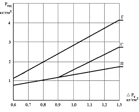
A drawback of using the mode switch is that the railway worker must walk along the entire train, crawl under each carriage, and switch the mode lever to the required position. According to sources from operations, this is not always done. Excessive filling of brake cylinders on an unloaded carriage can lead to wheel slip, reduced braking efficiency, and damage to wheelsets. To address this situation, a so-called automatic mode (AM), which mechanically determines the mass of the carriage and smoothly regulates the maximum pressure in the brake cylinder, is included between the air distributor and the brake cylinder. If a carriage is equipped with automatic mode, the mode switch on the AD is set to the "loaded" position.
Braking is usually performed in stages. The minimum stage of pressure reduction in the brake line for the VR483 is 0.06 to 0.08 MPa. At this point, a pressure of 0.1 MPa is established in the brake cylinders. The engineer sets the valve to the cutoff position, where the pressure established after braking is maintained in the brake line. If the braking efficiency from one stage is insufficient, the next stage is executed. At this point, the air distributor does not care about the pace of the reduction — as the pressure decreases at any rate, the filling of the brake cylinders occurs proportionally to the amount of pressure decrease.
The complete release of the brakes (complete emptying of the brake cylinders on the entire train) is performed by raising the pressure in the brake line above the charging level. Moreover, in freight trains, a significant increase in pressure in the brake line above the charging level is performed to ensure that the pressure wave reaches the very last cars. The complete release of brakes in a freight train is a lengthy process and can take up to a minute.
The VR483 has two release modes: flat and mountain. In the flat mode, when the pressure in the brake line increases, a complete, continuous release occurs. In the mountain mode, a staged brake release is possible, which is not a complete emptying of the brake cylinders. This mode is applied when moving along a complex profile with a large inclination.
The air distributor 483 is, in general, a very interesting device. A detailed analysis of its design and operation is a topic for a separate large article. Here, we have covered the general principles of freight brake operation.
3. Pneumatic brakes of passenger type
Braking equipment of a passenger car: 1 — connecting hose; 2 — end valve; 3, 5 — connecting boxes of the electro-pneumatic brake line; 4 — stop valve; 6 — tube with wiring for the electro-pneumatic brake; 7 — insulated suspension of the connecting hose; 8 — dust collector; 9 — outlet to the air distributor; 10 — cutoff valve; 11 — working chamber of the electric air distributor; TM — brake line; VR — air distributor; EVR — electric air distributor; TC — brake cylinder; ZR — reserve tank
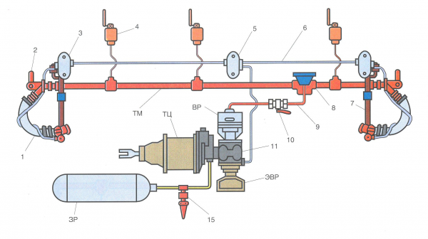
The larger amount of equipment immediately catches the eye, starting from the fact that there are three stop valves (one in each compartment, and one in the conductor's compartment), and ending with the fact that domestic passenger cars are equipped with both pneumatic and electro-pneumatic brakes (EPB).
The attentive reader will immediately note the main disadvantage of pneumatic brake control — the final speed of the braking wave, which is capped by the speed of sound. In practice, however, this speed is lower, at 280 m/s for service braking and 300 m/s for emergency braking. Moreover, this speed is heavily dependent on air temperature and in winter, for example, it is lower. Therefore, the eternal companion of pneumatic brakes is the unevenness of their operation across the train.
The unevenness of operation leads to two things — the occurrence of significant longitudinal reactions in the train, as well as an increase in braking distance. The first is not so characteristic for passenger trains, although the bouncing cups with tea and other drinks on the table in the compartment will not please anyone. However, the increase in braking distance is a serious problem, especially in passenger traffic.
Moreover, the domestic passenger air distributor—both the old type No. 292 and the new type No. 242 (of which, by the way, there are more and more in the fleet of passenger cars)—are direct descendants of the very same triple valve of Westinghouse, and they operate based on a difference of two pressures—in the brake line and the reserve tank. The distinguishing feature from the triple valve is the presence of a cutoff mode, meaning the ability for stepwise braking; the ability for additional discharge of the brake line during braking; the presence of an emergency braking booster in the design. These air distributors do not provide stepwise release—they give a complete release as soon as the pressure in the brake line exceeds the pressure in the reserve tank that was established there after braking. A stepwise release is very useful for adjustment braking to ensure precise stopping at the boarding platform.
Both problems—the uneven braking action and the lack of stepwise release—on a 1520 mm gauge are solved by installing an air distributor with electric control on the cars— electric air distributor (EAD), type No. 305.
The domestic EPТ—electric-pneumatic brake—is direct acting and non-automatic. On passenger trains with locomotive traction, the EPТ operates on a two-wire system.
The structural diagram of the two-wire EPТ: 1—master controller on the driver's valve; 2—battery; 3—static power converter; 4—indicator lamp panel; 5—control unit; 6—terminal block; 7—connecting heads on the hoses; 8—insulated suspension; 9—semiconductor valve; 10—release electromagnetic valve; 11—brake electromagnetic valve.
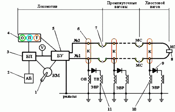
Two wires run along the entire train: No. 1 and No. 2 as shown in the diagram. On the rear car, these wires are electrically connected and an alternating current of 625 Hz is passed through the resulting loop. This is done to monitor the integrity of the EPТ control line. If the wire breaks, the alternating current circuit is interrupted, and the driver receives a signal in the form of the 'O' (release) indicator lamp going out in the cabin.
Management is conducted with direct current of varying polarity. In this case, the rails serve as the zero-potential conductor. When a positive voltage (relative to the rails) is applied to the conductor of the Electro-Pneumatic Transmitter (EPT), both electromagnetic valves installed in the electro-pneumatic distributor are activated: the release valve (RV) and the brake valve (BV). The first isolates the working chamber of the electro-pneumatic distributor from the atmosphere, while the second fills it from the backup reservoir. Next, the pressure relay installed in the EPR comes into play, operating based on the pressure difference in the working chamber and the brake cylinder. When the pressure in the working chamber exceeds the pressure in the brake cylinder, air is supplied to the latter from the backup reservoir until it reaches the pressure accumulated in the working chamber.
When a negative potential is applied to the conductor, the brake valve turns off, as the current to it is cut off by a diode. Only the release valve remains active, maintaining pressure in the working chamber. This realizes the shut-off position.
When the voltage is removed, the release valve loses power and opens the working chamber to the atmosphere. As the pressure in the working chamber decreases, the pressure relay releases air from the brake cylinders as well. If, after a brief release, the driver returns the valve to the shut-off position, the drop in pressure in the working chamber will stop, and the release of air from the brake cylinder will cease. This allows for stepwise brake release.
What happens if the wire breaks? Correct — the EPT will release. Therefore, this brake (on domestic rolling stock) is not automatic. If the EPT fails, the driver can switch to pneumatic control of the brakes.
The EPT features simultaneous filling of the brake cylinders and their emptying throughout the train. The filling and emptying rate is quite high at 0.1 MPa per second. The EPT is an inexhaustible brake, as during its operation, the standard air distributor remains in release mode and feeds the backup reservoirs from the brake line, which in turn is replenished by the driver's valve on the locomotive from the main reservoirs. Therefore, the EPT can be applied at any frequency required for operational control of the brakes. The ability for incremental release allows for very precise and smooth control of the train's speed.
The pneumatic control of the passenger train's brakes is not much different from that of a freight brake. There is a difference in management methods; for example, the release of the pneumatic brake occurs up to the working pressure, without overshooting. Generally, excessive overshooting of pressure in the brake line of a passenger train is fraught with problems, so at full release, the pressure in the brake line is elevated by a maximum of 0.02 MPa above the set working pressure.
The minimum discharge depth in the brake line when braking with the passenger brake is 0.04 to 0.05 MPa, with a pressure of 0.1 to 0.15 MPa created in the brake cylinders. The maximum pressure in the brake cylinder of a passenger car is limited by the volume of the backup reservoir and usually does not exceed 0.4 MPa.
Conclusion
Now I would like to address some commentators who are surprised (and, in my opinion, even outraged, though I wouldn't assert that) by the complexity of the train brake. In the comments, it is suggested to apply an automotive scheme with energy accumulators. Of course, from a couch or an office chair, many problems seem clearer and their solutions more obvious through a browser window, but I must note that most technical solutions adopted in the real world are based on clear reasoning.
As already mentioned, the main problem of pneumatic brakes in trains is the final speed of the pressure drop wave traveling through the long (up to 1.5 km in a 100-car train) brake pipe — the brake wave. Additional discharge is required to accelerate this brake wave, which is performed by the air distributor. Without the air distributor, there will be no additional discharge. This means brakes using energy accumulators will clearly perform worse in terms of activation consistency, taking us back to the days of Westinghouse. A freight train is not a cargo truck; it operates on a different scale, and thus, the principles of brake management are different. I'm sure this is not coincidental, and the direction of global brake science has led us to these types of designs.
This article serves as an overview of the existing braking systems on modern rolling stock. In subsequent articles of this series, I will delve deeper into each of them. We will learn about the devices used for brake control, how air distributors are structured, and examine the issues of regenerative and rheostatic braking in greater detail. Of course, we will also consider the brakes of high-speed transport. Until next time, and thank you for your attention!
P.S.: Friends! I want to express a special thanks for the numerous personal messages pointing out errors and typos in the article. Yes, I am a sinner who struggles with the Russian language and gets confused on the keyboard. I have tried to correct your remarks.
Source: habr.com
