

It's time to talk about devices designed for brake control. These devices are called 'valves', although a long evolutionary path has taken them quite far from what we typically understand as valves, transforming them into quite complex pneumatic automation devices.
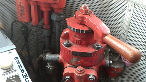
The good old spool valve 394 is still in use on rolling stock.
1. Engineer's Valves — A Brief Introduction
By definition
The train engineer's valve is a device (or a set of devices) designed to control the magnitude and rate of pressure change in the train's brake line.
Current train engineer's valves can be divided into direct control devices and remotely controlled valves.
Direct control devices are the classics, installed on the vast majority of locomotives, multiple units, and also on specialized rolling stock (various road machines, railcars, etc.) are the engineer's valves No. 394 and No. 395. The first one, shown in the KDPV, is installed on freight locomotives, while the second is used on passenger trains.
In pneumatic terms, these valves do not differ from each other at all. They are absolutely identical. The 395 valve has, cast as part of its upper section, a projection with two threaded holes where the 'bank' of the electro-pneumatic brake control is installed.
The 395 engineer's valve in its natural habitat.
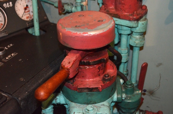
These devices are often painted bright red, indicating their exceptional importance and the special attention that both the locomotive crew and the technological personnel servicing the locomotive should pay to them. Another reminder that the brakes on the train are everything.
The feed line (PM) and brake line (TM) pipes are directly connected to these devices, and by turning the handle, direct control of the airflow is achieved.
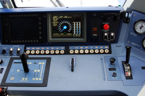
In remote-controlled cranes, the so-called control controller is not the crane itself; instead, it transmits commands to a separate electro-pneumatic panel, which is installed in the locomotive's machine room via a digital interface. The domestic rolling stock uses the much-criticized crane for the driver of class No. 130, which has been trying to establish itself in the rolling stock for quite some time.
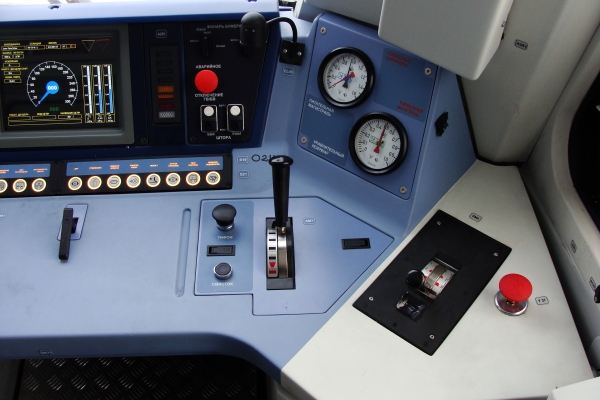
The controller for crane No. 130 on the cab of the EP20 electric locomotive (on the right, next to the manometer panel)
Pneumatic panel in the machine room of the EP20 electric locomotive
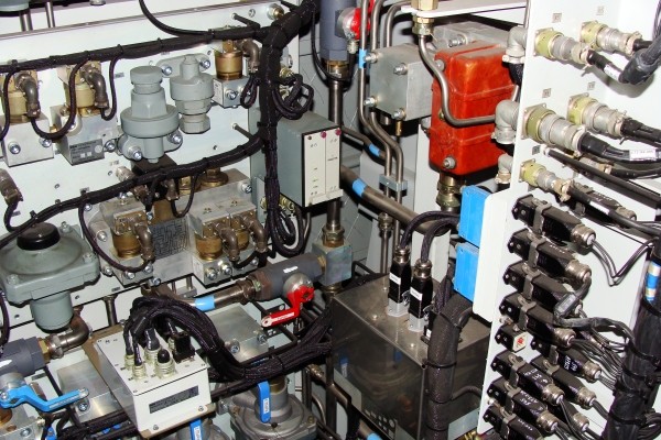
Why was it designed this way? To provide a standard way to manage automatic brakes in addition to manual control, for example, from the train control system. On locomotives equipped with the 394/395 crane, a special attachment was required on the crane for this purpose. The idea was that the 130 crane would be integrated into the train control system via the CAN bus, which is used in domestic rolling stock.
Why did I call this device much-criticized? Because I witnessed its first appearance on rolling stock. Such devices were installed on the first models of new Russian electric locomotives: 2ES5K-001 "Yermak", 2ES4K-001 "Donchak", and EP2K-001.
In 2007, I participated in the certification tests of the 2ES4K-001 electric locomotive. On this machine, the 130 crane was specifically installed. However, even then, there were talks about its low reliability; moreover, this technological marvel could spontaneously release the brakes. Therefore, it was soon abandoned, and the "Yermaks", "Donchaks", and EP2Ks went into production with 394 and 395 cranes. Progress was postponed until a new device was developed. This crane returned to the Novocherkassk locomotives only when the EP20 electric locomotive began production in 2011. By the way, the EP2K-001 with the 130 crane is currently decaying at the storage base, as I recently learned from a video by a railway enthusiast.
However, the railway workers do not fully trust such a system; hence, all locomotives equipped with the crane No. 130 are also fitted with backup control cranes, which allow for simplified direct control of the pressure in the brake pipeline.
Backup brake control valve in the driver's cabin of EP20
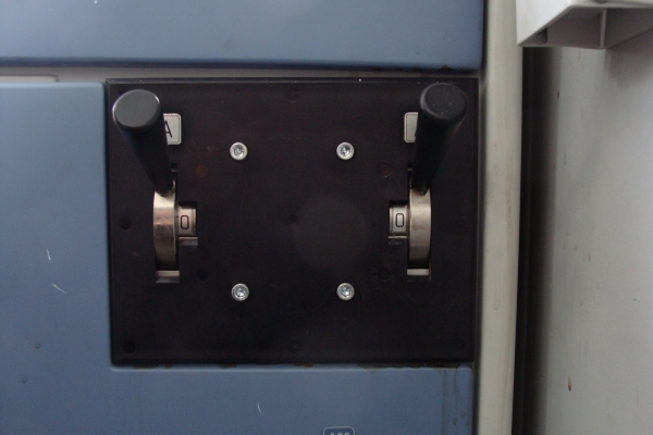
Locomotives also have a second control device installed — auxiliary brake valve (KVT), designed to control the locomotive brakes independently of the train brakes. Here it is, to the left of the train valve
Auxiliary brake valve, model No. 254
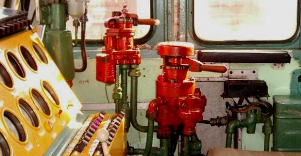
The photo shows a classic auxiliary brake valve, model No. 254. It is still widely installed on both passenger and freight locomotives. Unlike the wagon brakes, the brake cylinders on the locomotive never are not directly filled from the storage reservoir. Although both the storage reservoir and the air distributor are installed on the locomotive. In general, the braking system of the locomotive is more complex because there are more brake cylinders on the locomotive. Their total volume significantly exceeds 8 liters, so it will not be possible to fill them from the storage reservoir to a pressure of 0.4 MPa — it is necessary to increase the volume of the storage reservoir, which will increase its charging time compared to the wagon's SR.
On the locomotive, the cylinders are filled from the main reservoir, either through the auxiliary brake valve or through a pressure relay that is acted upon by the air distributor activated by the driver's train valve.
Valve 254 has the particular feature that it can also operate as a pressure relay, allowing for the release (stepwise!) of the locomotive brakes when the train is halted. This system is called the KVT switching scheme as a repeater and is used on freight locomotives.
The auxiliary brake valve is used during shunting movements of the locomotive, as well as for securing the train after stopping and during standing. Immediately after the train stops, this valve is set to the final braking position, and the train's brakes are released. The locomotive's brakes can hold both the locomotive and the train on quite a significant incline.
Modern electric locomotives, such as the EP20, are equipped with different KVT models, for example, model No. 224
Auxiliary brake valve model No. 224 (on the right side of a separate panel)
2. Structure and principle of operation of the driver's valve model No. 394/395
So, our hero is the old, tried-and-true crane 394 (and 395, but it's similar, so I will refer to one device while meaning the other). Why this one and not the modern 130? First, the 394 crane is more common today. Second, the 130 crane, or rather its pneumatic panel, functions similarly to the old-timer 394.
Driver's crane, model No. 394: 1 — outlet valve base; 2 — lower housing; 3 — sealing sleeve; 4 — spring; 5 — outlet valve; 6 — sleeve with outlet valve seat; 7 — balancing piston; 8 — rubber sealing sleeve; 9 — brass sealing ring; 10 — middle housing; 11 — upper housing; 12 — spool; 13 — control handle; 14 — handle lock; 15 — nut; 16 — clamping screw; 17 — rod; 18 — spool spring; 19 — clamping washer; 20 — mounting studs; 21 — locking pin; 22 — filter; 23 — supply valve spring; 24 — supply valve; 25 — sleeve with supply valve seat; 26 — diaphragm of the reducer; 30 — adjusting spring of the reducer; 31 — adjusting cup of the reducer.
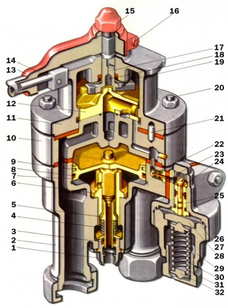
What do you think? A serious device. This device consists of an upper (spool) part, a middle (intermediate) part, a lower (balancing) part, a stabilizer, and a reducer. The reducer is shown at the bottom right of the figure; I will show the stabilizer separately.
Stabilizer for driver's crane model No. 394: 1 — plug; 2 — throttle valve spring; 3 — throttle valve; 4 — throttle valve seat; 5 — calibrated hole with a diameter of 0.45 mm; 6 — diaphragm; 7 — stabilizer housing; 8 — stop; 10 — adjusting spring; 11 — adjusting cup.
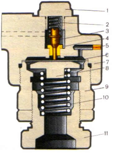
The crane's operating mode is set by turning the handle, which rotates the spool tightly fitted (and thoroughly lubricated!) to the mirror in the middle part of the crane. There are seven positions, traditionally denoted by Roman numerals.
- I — release and charging
- II — train operation
- III — closure without supply to leak in the brake line
- IV — closure with supply to leaks from the brake line
- Va — braking at a reduced pace
- V — braking at the service pace
- VI — emergency braking
In traction mode, during coasting and at a standstill, when it is not necessary to engage the train brakes, the handle of the valve is set to the second train position.
The valve and the valve mirror contain channels and calibrated holes through which, depending on the position of the handle, air flows from one part of the device to another. This is what the valve and its mirror look like.
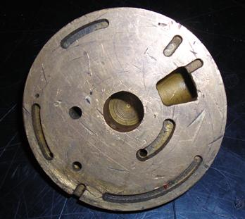
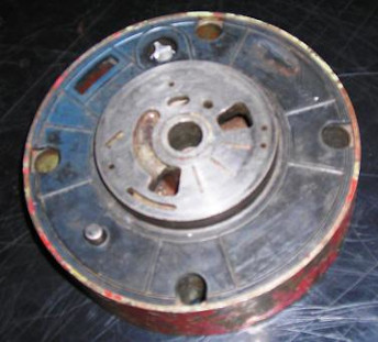
In addition, the driver's valve 394 is connected to the so-called equalizing reservoir (ER) with a volume of 20 liters. This reservoir serves as the pressure setter in the brake line (BL). The pressure established in the equalizing reservoir will be maintained by the equalizing part of the driver's valve and in the brake line (except for positions I, III, and VI of the handle).
The pressures in the equalizing reservoir and the brake line are displayed on control manometers located on the dashboard, usually next to the driver's valve. A dual-pointer manometer is often used, like this one:
The red needle shows the pressure in the brake line, while the black one shows the pressure in the equalizing reservoir.
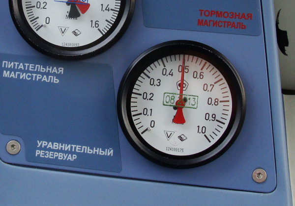
So, when the valve is in the train position, a so-called charging pressureis established and maintained in the equalizing reservoir. For railcar and passenger trains with locomotive traction, its value is typically 0.48 — 0.50 MPa, and for freight trains 0.50 — 0.52 MPa. However, it is most often 0.50 MPa, the same pressure used in the 'Sapsan' and 'Lastochka.'
Devices that support the pressure in the equalizing reservoir are the regulator and the stabilizer valve, which operate completely independently of each other. What does the stabilizer do? It continuously releases air from the equalizing reservoir through a calibrated orifice with a diameter of 0.45 mm located in its body. This process is constant, uninterrupted for even a moment. The air release through the stabilizer occurs at a strictly constant rate, maintained by the throttle valve inside the stabilizer — the lower the pressure in the equalizing reservoir, the more the throttle valve opens. This rate is much lower than that of service braking, and it can be adjusted by turning the adjustment cup on the stabilizer's body. This is done to eliminate pressure in the equalizing reservoir. overcharged (i.e., exceeding charging) pressure.
If air is constantly leaving the equalizing reservoir through the stabilizer, it will eventually run out, right? It would run out, but the regulator won't allow it. When the pressure in the equalizing reservoir drops below the charging pressure, the feeding valve in the regulator opens, connecting the equalizing reservoir with the supply line, replenishing the air supply. Thus, in the equalizing reservoir, with the valve handle in the II position, a pressure of 0.5 MPa is continuously maintained.
This process is best illustrated by the following diagram.
Operation of the driver’s valve in the II (train) position: GR — main reservoir; TM — brake line; UR — equalizing reservoir; At — atmosphere.

And what about the brake line? The pressure in it is maintained equal to the pressure in the equalizing reservoir through the equalizing part of the valve, which consists of an equalizing piston (in the center of the diagram), a feeding valve, and a release valve, activated by the piston. The cavity above the piston is connected to the equalizing reservoir (yellow area), and below the piston — with the brake line (red area). When the pressure in the equalizing reservoir increases, the piston moves down, connecting the brake line to the supply line, causing the pressure in it to rise, until the pressure in the TM and the pressure in the UR become equal.
When the pressure in the equalizing reservoir decreases, the piston moves up, opening the exhaust valve through which air from the brake line escapes into the atmosphere, until the pressures above and below the piston are equalized again.
Thus, in the traveling position, the pressure in the brake line is maintained equal to the charging pressure. This includes feeding and leaks from it, as I constantly emphasize, there are definitely and always leaks present in it. The same pressure is established in the auxiliary reservoirs of the cars and locomotive, also accounting for leakages.
To activate the brakes, the engineer places the valve handle in the V position — braking at the service rate. At this time, air is released from the equalizing reservoir through a calibrated orifice, ensuring a pressure drop rate of 0.01 — 0.04 MPa per second. This process is monitored by the engineer using the pressure gauge of the equalizing reservoir. As long as the valve handle remains in the V position, air continues to escape from the equalizing reservoir. The equalizing piston actuates, rising upwards and opening the exhaust valve, releasing pressure from the brake line.
To stop the release of air from the equalizing reservoir, the engineer places the valve handle in the cut-off position — III or IV. The release of air from the equalizing reservoir, and consequently from the brake line, stops. This completes the service braking step. If the brakes are insufficiently effective, another step is performed, for which the engineer's valve handle is again switched to position V.
In normal operation, service In braking, the maximum depth of the vacuum in the braking system must not exceed 0.15 MPa. Why? Firstly, a deeper vacuum is pointless — due to the ratio of the volumes of the reserve tank and the brake cylinder (BC), the pressure in the BC cannot exceed 0.4 MPa. The vacuum of 0.15 MPa corresponds to a pressure of 0.4 MPa in the brake cylinders. Secondly, deeper vacuuming is simply dangerous — at low pressure in the braking system, the time to recharge the reserve tanks upon releasing the brakes will increase, as they are charged directly from the braking system. Such actions risk the brake being exhausted.
A curious reader may ask — how do the shutoff positions III and IV differ?
In position IV, the valve of the tap completely blocks all openings in the mirror. The reducer does not draw from the equalizing tank, and the pressure in it remains quite stable, as leaks from the ET are minimal. The equalizing piston continues to work, replenishing leaks from the braking system, maintaining the pressure that was established in the equalizing tank after the last braking. Therefore, this position is called ‘shutoff with replenishment of leaks from the braking system’
In position III, the valve of the tap connects the cavities above and below the equalizing piston, which blocks the operation of the equalizing organ — the pressure in both cavities drops simultaneously at the rate of leakage. There is no replenishment of this leakage by the equalizing organ. Therefore, position III of the tap is called ‘shutoff without replenishment of leaks from the braking system’
Why are there two such positions and which shutoff does the driver use? Both, depending on the situation and the type of service of the locomotive.
When managing passenger brakes, according to instructions, the driver must set the tap to position III (shutoff without replenishment) in the following cases:
- When proceeding under a stop signal
- When operating the EPT after the first stage of regulation braking
- When traveling downhill or into a dead-end
In all these situations, a spontaneous release of the brakes is unacceptable. But how can it happen? It's quite simple — passenger air distributors operate based on the difference between two pressures — in the brake line and the backup reservoir. When the pressure in the brake line increases, the brakes are fully released.
Now, imagine that we have braked and set to position IV, when the tap feeds leaks from the brake line. At that time, some idiot in the vestibule opens and then closes the stop valve — just playing around. The driver's tap drains this leak, leading to an increase in pressure in the brake line, and the sensitive passenger air distributor gives a full release.
In freight trains, mainly position IV is used — freight air distributors are not as sensitive to pressure increases in the brake line and have a firmer release. Position III is only set when there is suspicion of unacceptable leakage in the brake line.
How is the brake release performed? For a full release, the driver’s lever is set to position I — release and charging. In this case, both the equalizing reservoir and the brake line are connected directly to the supply line. However, filling the equalizing reservoir is done through a calibrated hole at a fast but sufficiently moderate pace, allowing pressure control via the gauge. The filling of the brake line is carried out through a wider channel, causing the pressure to immediately jump to 0.7 — 0.9 MPa (depending on the length of the train) and to be maintained until the lever is moved to the second position. Why is this so?
This is done to push a large volume of air into the brake line, sharply increasing the pressure in it, which ensures that the release wave reaches the last car without fail. This effect is called impulse supercharging. It allows both the release itself to be accelerated and ensures a quicker charging of the backup reservoirs throughout the train.
Filling the equalizing reservoir at a specified rate allows the release process to be controlled. Upon reaching the pressure in it charging (for passenger trains) or slightly elevated, depending on the length of the train (for freight), the handle of the driver's valve is set to the II train position. The stabilizer eliminates the overcharging of the equalizing reservoir, and the equalizing piston quickly equalizes the pressure in the braking main line to that in the equalizing reservoir. This is how the complete release process of the brakes to charging pressure looks from the engineer's point of view.
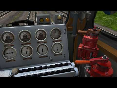
Step release, in the case of controlling the EPV or on freight trains in mountain operation mode of the air distributor, is performed by setting the handle of the valve to the II train position, followed by switching to the bypass.
How is the electro-pneumatic brake managed? The EPV is controlled from the same driver's valve, specifically the 395 model, which is equipped with an EPV controller. In this "bank" fitted on top of the valve handle, there are contacts that control the supply to the EPV lead of a positive or negative potential relative to the rails through the control block, as well as disconnecting this potential for brake release.
With the EPV engaged, braking is performed by placing the driver's valve in the Va position — soft braking. At this moment, the braking cylinders are filled directly from the electric air distributor at a rate of 0.1 MPa per second. The process is monitored using a pressure gauge in the braking cylinders. The equalizing reservoir is discharged during this time, but rather slowly.
The release of the EPV can be performed either in steps by placing the valve in position II or completely by placing it in position I and increasing the pressure in the equalizing reservoir by 0.02 MPa above the charging pressure. This is roughly how everything looks from the engineer's perspective.
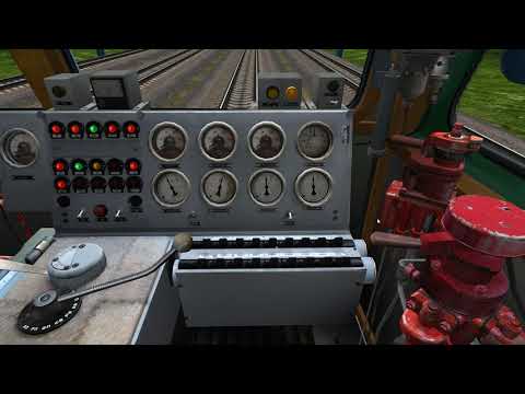
How is emergency braking performed? When the driver's brake handle is set to position VI, the valve opens a wide channel, directly releasing the brake line to the atmosphere. The pressure drops from charged to zero in 3-4 seconds. The pressure in the equalizing reservoir also decreases, but more slowly. At the same time, the emergency brake actuators activate on the air distributors—each valve opens the brake line to the atmosphere. Sparks fly from the wheels, the wheels skid, despite the sand being spread underneath them...
For every such 'throwing into six' the driver faces an investigation at the depot—whether their actions were justified by the Brake Control Instruction and the Rules for the Technical Operation of Rolling Stock, as well as a number of local instructions. Not to mention the stress they experience when 'throwing into six.'
Therefore, if you go onto the tracks, speeding past a closing barrier at a level crossing in a car, remember that for your mistake, foolishness, whim, and bravado, ultimately a living person—the train driver—bears the responsibility. And those people who will then have to deal with the sickening consequences...
I don't want to scare anyone, but it's true—truth written in blood and colossal material losses. Hence, the train's brakes are not as simple as they might seem.
Summary
I will not consider the work of the auxiliary brake's valve in this article. For two reasons. Firstly, this article is saturated with terminology and dry engineering, barely fitting within the framework of popular science. Secondly, addressing the operation of the KVT requires a description of the nuances of the locomotive's brake pneumatic scheme, which is a topic for another conversation.
I hope this article instilled a superstitious fear in the readers… no, no, I’m just joking. Seriously, I believe it's clear that train braking systems are a complex set of interconnected and extremely intricate devices, designed for the operational and safe management of rolling stock. Moreover, I very much hope that I deterred someone from joking with the locomotive crew by playing with the emergency brake. At least for someone...
In the comments, I've been asked to talk about the 'Sapsan'. There will be a 'Sapsan', and it will be a separate, good, and large article, with very detailed specifics. This electric train gave me a brief but creatively rich period in my life, so I really want to share about it, and I will definitely fulfill my promise.
I want to express my gratitude to the following people and organizations:
- Roman Biryukov (Romych RZhDUZ) for the photo material on the EP20 cab
- Site — for the diagrams taken from their resource
- Once again, thanks to Roma Biryukov and Sergey Avdonin for the consultations on the nuances of brake operation
Until we meet again, dear friends!
Source: habr.com
