

Next time you find yourself at the station, take a moment to notice the inscription right in the middle at the bottom of the train car you'll be boarding for your much-anticipated vacation. This inscription isn't there by chance; it informs us of the mysterious, conditional number of the brake air distributor installed on this car.
The inscription is visible even if the train is standing at a high platform, so don't miss it.
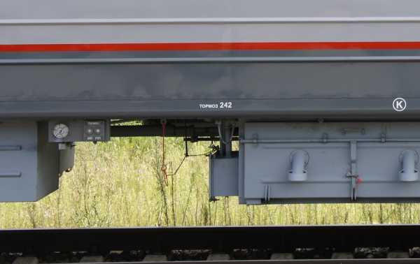
On this car — 'Amendorff', which has undergone a major overhaul at the Tver Carriage Engineering Plant, an air distributor (AD) with conditional number 242 of the passenger type has been installed. It is now being installed on all new and 'overhauled' cars, replacing the earlier 292 AD. Today, we will discuss these devices, which belong to the family of braking instruments.
1. Heirs of Westinghouse
Passenger-type air distributors used on railways with a gauge of 1520 mm are a kind of compromise between the simplicity of design inherited from Westinghouse's triple valve and the demands for safety in operation. They have not undergone as lengthy and dramatic a development path as their freight counterparts.
Currently, two models are in use: air distributor with conditional number 292 and the rapidly emerging alternative (at least in the RZD carriage fleet) air distributor with conditional number 242.
These devices differ in design but are practically similar in their operational properties. Both devices operate on the difference in two pressures — in the brake pipeline (BP) and the reserve tank (RT). Both provide additional discharge of the brake pipeline during braking: the 292 discharges the BP into a special closed chamber (discharge chamber), with a volume of 1 liter, while the 242 discharges directly into the atmosphere. Both devices are equipped with an emergency braking accelerator. Neither of the devices features a step release — they both release immediately when the pressure in the BP exceeds the pressure in the RT, which has been established there after the last braking, as they say, they have a 'soft' release.
The lack of a staged release is compensated by the fact that both devices do not operate on the wagon alone (although they can), but in conjunction with the electric air distributor No. 305, which introduces electric control of the brakes, and the working chamber with a pneumatic relay, providing the possibility of staged release.
As an example, let's consider the VR 242, as a more modern model, and also the EVR 305.
The brand new VR 242 on the pneumatic panel in the machine compartment of the EP20 electric locomotive.
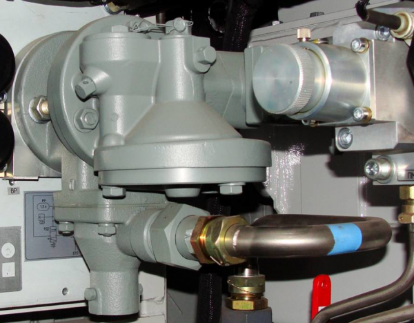
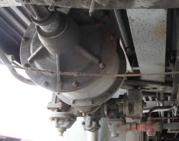
The same, installed on a passenger car.
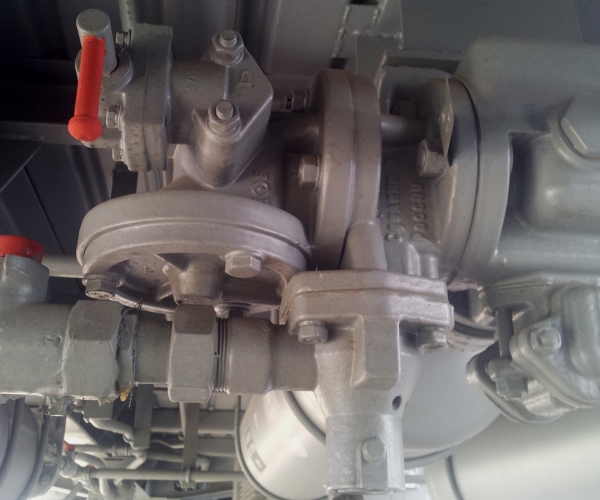
Now let's turn to the design and principle of operation of this device.
The diagram explaining the design of the VR 242: 1, 3, 6, 16 — calibrated holes; 2, 4 — filters; 5 — discharge limiting piston TM;
7, 10, 13, 21, 22 — springs; 8 — exhaust valve; 9 — hollow rod; 11 — main piston; 12 — additional discharge valve; 14 — mode switch stop; 15 — mode switch piston; 17, 28 — rods; 18 — brake valve; 19 — relief valve; 20 — emergency braking switch stop; 23, 26 — valves; 24 — hole; 25 — emergency brake accelerator piston; 27 — additional discharge limiting valve; UC — accelerator chamber; ZK — spool chamber; MK — main chamber; TM — brake line, ZR — reserve tank; TC — brake cylinder.
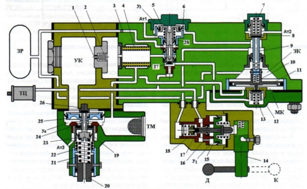
How does the air distributor begin its operation? It starts with charging, that is, filling the chambers of the air distributor and the reserve tank with compressed air from the brake line. These processes occur when the locomotive is started in the depot when it stands without air, as well as on all cars when they are coupled to the locomotive, and the end valve is opened — taking the train "on air." Let's examine this process in more detail.
The operation of the VR 242 during charging.
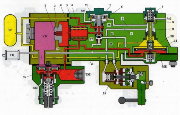
Thus, air from the brake line, at a pressure of 0.5 MPa, flows into the device, filling chamber U4 under the accelerator piston, then it moves up through the channel (shown in red), through filter 4, into the main chamber (MC), supporting the main piston 11 from below. It rises, and its hollow rod 9 opens the exhaust valve 8, connecting the brake cylinder cavity to the atmosphere. Simultaneously, air from the filter, through the axial rod channel 28, passes through calibrated hole 3 into the reserve tank (shown in yellow), and from there, through the channel into the valve chamber (VC) above the main piston 11.
This process continues until the pressure in the reserve tank, main chamber, and valve chamber equals the charging pressure in the brake line. The main piston will return to the neutral position, closing the exhaust valve. The air distributor is ready for action.
Let me reiterate — the pressure in the BL is unstable; there are leaks, small leaks, but they are always present. This means that the pressure in the BL can decrease. If the pressure drop occurs at a rate slower than the service rate, the air from the valve chamber can flow into the main chamber through throttle 3, keeping the main piston in place, and braking does not occur.
With a decrease in pressure in the brake line at the service braking rate, the pressure in the MC drops quickly enough for the main piston to move downward due to the greater pressure in the valve chamber. As it moves down, it opens the additional discharge valve 12.
Action VR 242 during braking: phase of additional discharge of the BL
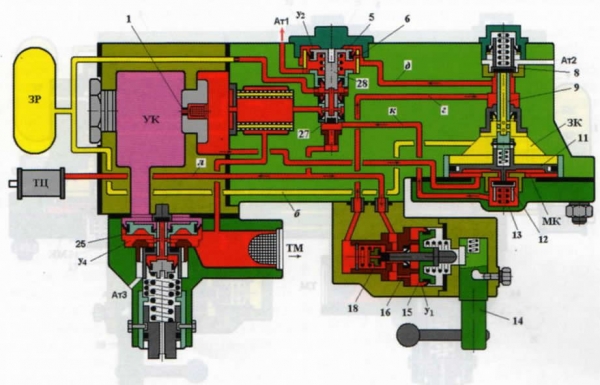
Air from the main chamber, through valve 12 via channel K, exits to the atmosphere through the axial channel of rod 28. The pressure in the brake line and main chamber decreases even more rapidly, and piston 11 continues its downward movement.
Action VR 242 during braking: initial filling of the brake cylinder
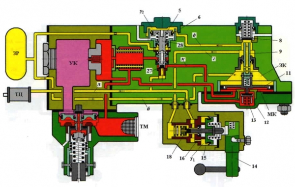
The hollow rod of the main piston 9 moves away from the seal on the exhaust valve, thus opening the way for air from the reserve tank, which passes through channel B into the valve chamber, the axial channel of rod 9, channel G and the mode switch, flowing into the brake cylinder through channel L. Simultaneously, the same air passes through channel D into chamber U2, pressing on piston 6, which cuts off the atmosphere from the additional discharge channel. The additional discharge is stopped. At the same time, the rod 28 of piston 6 moves down, the radial channels in it are blocked by rubber seals, which leads to the disconnection of the main and valve chambers. This increases the sensitivity of the air distributor to braking — now a decrease in pressure in the brake main line at any rate will lead to the lowering of the main piston and the filling of the brake cylinder.
The action of VR 242 during braking: switching the filling rate of the brake cylinder.

At the beginning, the brake cylinder fills quickly, through the wide channel, via the open brake valve 18. As the brake cylinder fills, chamber U1 of the mode switch is filled through the calibrated hole 16. When the pressure becomes sufficient to compress the spring under piston 15, the brake valve closes, and the brake cylinder fills through the calibrated hole in the brake valve at a slowed rate. This happens if the mode switch handle 14 is turned to position 'D' (long train). This mode is used if the number of cars in the train exceeds 15. This is done to slow down the filling of the brake cylinder on the cars, ensuring more uniform braking across the train.
In short trains, the handle 14 is set to position 'K' (short train). This mechanically opens the brake valve 18, and the filling of the brake cylinder occurs at a fast rate all the time.
When the driver sets the valve to the shutoff position, the pressure drop in the brake line stops. The filling of the brake cylinder will continue until the pressure in the backup reservoir drops to the point where it equals the pressure in the main chamber and the brake line. The main piston will return to its neutral position. The filling of the brake cylinder ceases, and the shutoff occurs.
To release the brakes, the driver sets the valve handle to position I. Air from the main reservoirs rushes into the brake line, significantly increasing the pressure within it (to 0.7 - 0.9 MPa, depending on the length of the train). The pressure in the main chamber also rises, causing the main piston to move upward and the discharge valve 8 to open, allowing air from the brake cylinders and chamber U2 to escape into the atmosphere. The pressure drop in chamber U2 causes the piston 6 and rod 28 to rise, and the brake line and backup reservoir reconnect through throttle 3, allowing the backup reservoir to charge.
Upon reaching the charging pressure in the equalizing reservoir (UR) equal to the charging pressure, the driver sets the valve to position II (train position). The pressure in the brake line quickly restores to the level of pressure in UR. However, due to throttle 3, the pressure in the backup reservoir has not yet managed to reach the charging pressure; the charging of the backup reservoir continues, albeit at a slower rate. Gradually, the pressure in the backup reservoir, the main chamber, and the equalizing chamber will equal the charging pressure. Then the air distributor will be ready for a new braking action.
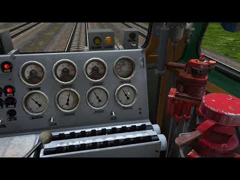
From the driver's perspective, the described processes appear as follows:
A separate component of the brake system 242 is the emergency braking actuator, which is located on the left side of the device in the diagram. During charging, along with filling the main part of the air distributor, the actuator is also charged—air fills the chamber below piston 25 and the chamber above the piston, through the acceleration chamber (AC). The brake line and acceleration chamber are connected via throttle hole 1, the diameter of which is such that during normal braking the pressure in the acceleration chamber manages to equalize with the pressure in the brake line, and the actuator does not activate.
Operation of the emergency braking actuator
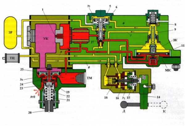
However, during a rapid drop in pressure—air escapes from the brake line in 3 to 4 seconds, the pressures do not have time to equalize, the air from the acceleration chamber pushes on piston 25, which opens the blow-off valve 19, creating a wide opening in the brake line, allowing air to escape into the atmosphere, exacerbating the process. Thus, during emergency braking, when the actuator operates, a window in the brake line opens for each car.
To disable the actuator (for example, in case of malfunction), a special key is used to turn the stop 20, which locks the acceleration piston in the upper position.
Despite the many written words and letters, this device has a fairly simple and reliable design in practice. Compared to its predecessor, the brake system 292, this one does not contain valves, which are quite capricious in operation, requiring fitting to a mirror and lubrication, and are also subject to wear.
The air distributor 242 is an autonomous device and can work without assistants. In practice, however, on passenger cars and locomotives, it operates in conjunction with another device called
2. Electric air distributor (EAD) No. 305
This device is designed for use in the electro-pneumatic brake system on passenger rolling stock. It is installed on cars and locomotives along with the brake systems 242 or 292. Here is what the brake equipment block looks like on a passenger car.
In the foreground is the brake cylinder. A bit further back, the working chamber of the EVR 305 is bolted to the rear wall of the TC. On the left, the electrical part of the EVR is connected along with the pressure relay, while on the right is the air distributor 292. Connected to it, through a shut-off valve, is the branch from the brake line (painted red).
The structure of the EVR 305: 1, 2, 3, 6, 9, 10, 11, 12, 14, 18 — air channels; 4 — exhaust valve; 5 — brake valve; 7 — atmospheric valve; 8 — feed valve; 11 — diaphragm; 13, 17 — cavities of the switch valve; 15 — switch valve; 16 — seal of the switch valve; TC — brake cylinder; RK — working chamber; OV — exhaust valve; TV — brake valve; ZR — reserve tank; VR — air distributor.
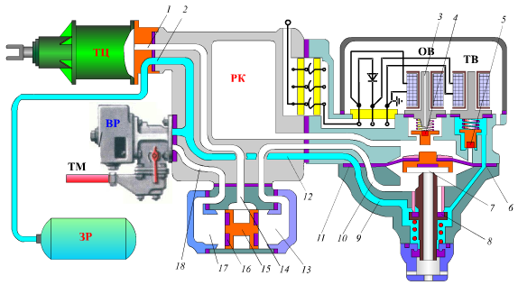
The EVR 305 consists of three main parts: the working chamber (RK), switch valve (PK), and pressure relay (RD). In the body of the pressure relay, the exhaust 4 and brake valves 5 are installed, controlled by electromagnets.
During charging, power is not supplied to the valves; the exhaust valve connects the working chamber cavity to the atmosphere, while the brake valve is closed. Air from the brake line passes through the air distributor to the channels inside the EVR into the reserve tank, charging it, but goes nowhere else since its path to the cavity above the diaphragm of the pressure relay is blocked by the closed brake valve.
Operation of the EVR 305 during charging
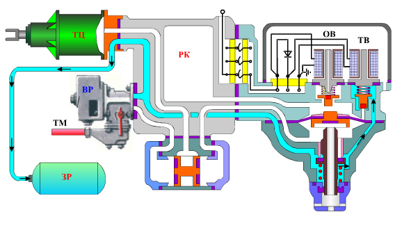
When the driver's valve is set to position Va, a positive potential (relative to the rails) is supplied to the EPT wire, and both valves receive power. The exhaust valve isolates the working chamber from the atmosphere, while the brake valve opens the path for air into the cavity above the diaphragm of the RD and further into the working chamber.
Operation of the EVR 305 during braking
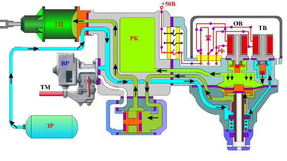
The pressure in the working chamber and in the cavity above the diaphragm increases, causing the diaphragm to bend downwards, opening the feed valve 8, through which air from the reserve tank first reaches the right cavity of the switch valve. The valve plug shifts left, opening the path for air into the brake cylinder.
When the driver's valve is set to the cutoff, the voltage supplied to the EPТ wire changes polarity, the diode powering the brake valve locks, the brake valve loses power, and the brake cylinder closes. Pressure in the working chamber ceases to increase, and the filling of the brake cylinder continues until the pressure inside equals the pressure in the working chamber. After this, the diaphragm returns to a neutral position, and the feed valve closes. A cutoff occurs.
Operation of EВP 305 during cutoff
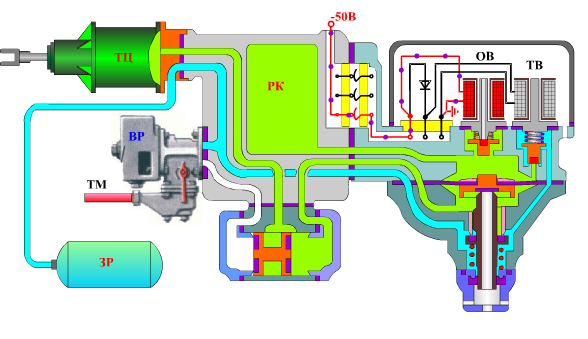
The release valve continues to receive power, keeping the release valve closed, preventing air from escaping the working chamber.
To release, the driver sets the valve handle to position I for full release and to II for incremental release. In both cases, the valves lose power, the release valve opens, letting air from the working chamber into the atmosphere. The diaphragm, supported from below by the pressure in the brake cylinder, moves upward, opening the discharge valve through which air escapes from the brake cylinder.
Operation of EВP 305 during release
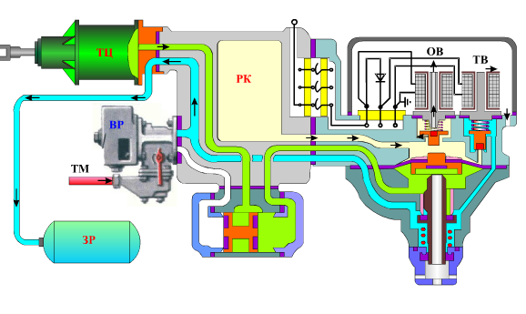
If, during release, the handle is set back to cutoff from the second position, air will stop escaping from the working chamber, and the emptying of the brake cylinder will continue until the pressure inside equals the pressure remaining in the working chamber. This enables incremental release.
Such an electro-pneumatic brake has several features. First, if the EPТ line is broken, the brakes will release. In this case, after carrying out a series of mandatory actions as prescribed by the instructions, the driver transitions to using the pneumatic brake. Thus, the EPТ is not an automatic brake. This is a drawback of this system.
Secondly, during the operation of the EPТ, the standard air distributor remains in the release position, continuously drawing off leaks from the reserve tank. This is advantageous, as it ensures the non-exhaustion of the electro-pneumatic brake.
Thirdly, this design does not interfere with the operation of a standard air distributor. If the EPT is off, the air distributor, filling the brake cylinder, will first fill the left chamber of the switching valve, shifting the plug in it to the right, thus opening the path for air from the reserve tank to the brake cylinder.
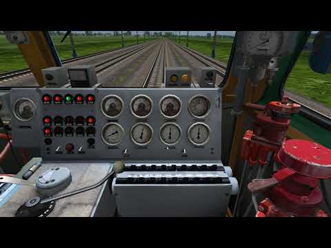
This is what the operation of the described systems looks like from the driver’s cabin:
Conclusion
I wanted to include freight braking devices in this article as well, but this topic requires a separate discussion, as freight air distributors are much more complex, utilizing more sophisticated technical solutions and tricks, dictated by the specifics of freight rolling stock operation.
As for the passenger brake, its similarity to the Westinghouse brake is compensated by additional technical solutions, which provide acceptable operational indicators, safety levels, and maintenance and repair technology for domestic rolling stock. It will be interesting to compare this with the question, 'How do they do it abroad?'. We will compare, but a bit later. Thank you for your attention!
P.S.: My thanks to Roman Biryukov for the photographic material, as well as to the site , from which the illustrative material was taken.
Source: habr.com
