


The final, most boring reference article. Reading it for general knowledge probably makes little sense, but when the time comes, it will be very helpful.
Contents of the article series
Subscriber's Territory
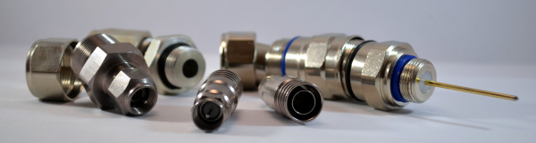
So, your grandmother's TV has stopped working. You bought her a new one, but it turned out the issue wasn't with the receiver — it's worth checking the cable. Firstly, it's not uncommon for screw connectors, which don't require crimping, to magically twist themselves onto the cable, leading to a loss of contact with the shielding or even the central conductor. Even if the connector was just crimped, you should ensure that none of the strands of the shielding are touching the central conductor. By the way, the diameter of the central conductor is usually noticeably thicker than the hole in the receiver's socket — this is necessary for good contact due to the spring-loaded petals in the connector. However, if you suddenly replaced the connector with one where the central conductor doesn’t come out 'as is', but instead transitions into a needle (like those I showed in connectors for RG-11), or if you changed a part of the cable and the new conductor turned out to be thinner, you may find that the tired petals in the socket do not provide good contact with the central conductor.
When measuring with a device, all of this can easily be seen by the slope of the signal spectrum, which I discussed in . This way, we can immediately check the signal level (which, I remind you, according to GOST should not be lower than 50 dBμV for digital signals and 60 for analog ones) and assess the attenuation in the low and high-frequency zones, which will give us hints for further troubleshooting.
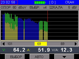
I remind you: attenuation of low frequencies is usually related to issues with the central conductor, while significant degradation of high frequencies indicates poor contact with the shielding, which is typically associated with the crimping (or generally poor condition of the cable, including excessive length).
After examining the cable connected to the television, it's important to trace it throughout the apartment. Since a coaxial cable is not just a conductor but a waveguide, breaks and other mechanical damage are not the only concerns; bends and kinks also matter significantly. Additionally, it’s essential to locate all signal splitters and calculate their total attenuation. It may turn out that everything was operating at the limit before, and even a slight degradation of the cable led to complete failure. In this case, to avoid re-running the hidden cable, it’s wiser to select the appropriate splitter values or install a small amplifier at the entrance to the apartment.
If none of this is observed and the cable is fine right up to the low-current panel on the staircase, then it's necessary to measure the signal level leaving the apartment. If the level and shape of the signal at the subscriber splitter are normal, it's worth assessing the difference between the values at the television and at the panel and to consider what we may have missed. If we see that the attenuation to the television is within a reasonable range but encounter signal issues at the output, we should proceed further.
Riser
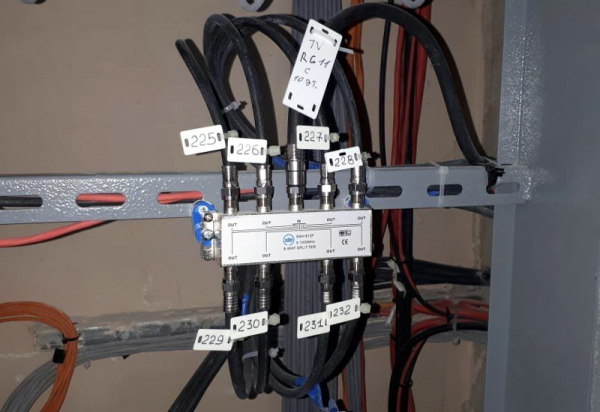
Upon identifying a problem at the subscriber output, one should verify that the splitter itself isn't at fault. It's not uncommon for one of the outputs to deteriorate signal quality either immediately or gradually, particularly in splitters designed for multiple subscribers (more than 4). To do this, measure the signal level at a different output (preferably as far away from the problematic one as possible) and also at the incoming trunk cable. Here, again, an understanding of what shape and level the signal should have is beneficial. The attenuation value indicated on the splitter’s labeling (e.g., 412 — 4 outputs at -12dB) must be subtracted from what was measured on the trunk. Ideally, we should arrive at the figure taken from the subscriber output. If it differs by more than a couple of dB, it’s better to replace that splitter.
If we see that the signal is already coming through the trunk with a strong tilt or low level, we will have to either familiarize ourselves with the riser project or, using logic, estimate two things: whether the riser is built from the top or the bottom and how far we are from the nearest branching point. The first can be understood from where the cable connected to the input of the splitter comes from and where the one from the output goes. It’s usually not difficult to trace trunk cables directly in the panel; if they are not visible, you can go to the floor above (or below) and see what the splitter there is rated at. you probably remember that as you move away from the beginning, the rating should decrease. I also wrote about dividing the riser into parts (we usually call them 'pilasters', I’m not sure if this term is widely accepted). Usually, one pilaster covers 5-6 floors, and at its beginning, there are splitters with ratings of 20-24 dB, while at the end — 8-10. Once there is confidence that the problem lies beyond the floor, you should find the start of the pilaster and take a measurement from the trunk splitter from which it begins. The problems are the same: both the splitter itself and a damaged cable or poor crimping can have an impact. Sometimes, after moving the connectors, the signal is restored (but more often it completely disappears). In this case, it is necessary to re-crimp everything, and it would be just wonderful if the installers anticipated this and left a cable reserve. After all, when re-crimping, it has to be shortened. The RG-11 cable is very commonly plagued by incorrect crimping: either the standard for stripping is not followed, leaving the center conductor too long (resulting in the connector being loosely fitted and the cable may slip out), or the same issue arises due to an excessively long section A (see diagram below).
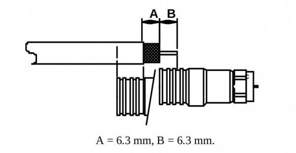
It’s worth mentioning separately that even proper stripping won’t prevent errors if the person crimping doesn’t fully seat the connector, causing the center conductor not to enter the connector's 'needle'. In this case, the needle can move if you shake it with your finger. When the conductor is well seated — it’s impossible to move it. This should be checked on every disconnectable connector.
In homes older than 10 years, something known among scale model collectors as 'zinc pox' can occur with the dividers.

Photo from the website
Divider cases made from obscure alloys and subjected to poor climatic conditions can literally crumble in your hands when attempting to unscrew a connector or even just when moving cables in the panel. This usually happens when installers are working in the panel, pulling internet for someone, or dealing with intercoms.
If the divider from which the pillar begins hasn't crumbled in half, and the signal level on it is just as poor as inside the apartment, you need to locate the first divider where branching occurs and measure the signal coming from the active equipment in the basement (or attic — depending on how it was built). If after this the riser issue isn't resolved, you'll have to seek out the active equipment and take measurements on it.
Active equipment
First of all, note that between optical receivers and amplifiers there is also a distribution network built on the same principles as the risers, and therefore having similar issues. Therefore, everything written above must also be checked here before assuming that the hardware is faulty.
So, we are in the basement (attic, electrical distribution room), in front of the amplifiers box.
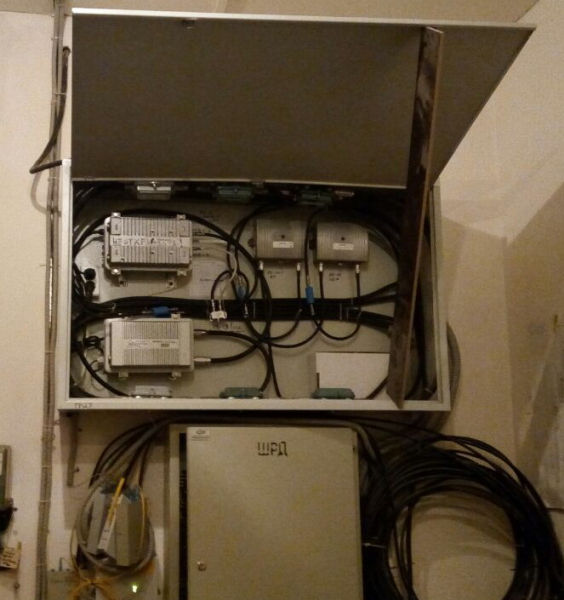
And this happens...
If there’s no signal in the riser at all and there’s a suspicion that the amplifier is dead, the easiest way to identify which one is by its temperature to the touch. Even in severe frosts, in unheated rooms, a functioning amplifier will be warmer than the surrounding environment, while a burnt-out one will feel cold. If the temperature difference is not sufficiently noticeable, opening it up will surely show that the power indicator inside the amplifier is not lit. Such an amplifier is replaced with a known working one, and later repaired with a regular soldering station, as most failures are related to common swollen capacitors. When replacing amplifiers with remote power, it’s necessary to de-energize the entire network to avoid short circuits. Although the voltage is not very high (60V), the current from that power supply I showed you... can deliver quite a show: when touching the central conductor, a significant spark effect is guaranteed. And while such amplifiers do not always survive power outages in the house, there is a non-zero chance that these special effects could damage several other devices, which would then need to be searched for throughout the house.
However, there are cases where the amplifier is alive, but at the same time it outputs a lot of noise to the network, or simply does not reach the required signal level as per the project (usually 110 dBμV). At the start, it’s essential to ensure that the incoming signal is not already damaged by measuring it. Some characteristic irreparable problems with amplifiers include the following:
- Reduction in gain. Due to the degradation of part or all of the amplification stage, we get the same signal level at the output as at the input (or higher, but insufficient for normal operation).
- Signal noise. The operation of the amplifier distorts the signal to the point that the output parameter Carrier/Noise (C/N) goes beyond the norm, hindering signal recognition by receivers.
- Disruption of the digital component of the signal. Sometimes the amplifier satisfactorily passes the analog signal, but completely fails to handle the digital one. Most often, the MER and BER parameters described in exceed permissible limits, turning the constellation into chaotic mush; interestingly, there are times when the amplifier forgets one of the modulation parameters, and instead of a constellation, it displays a ring or circle on the device's screen.
When these malfunctions occur, the amplifier needs to be replaced, but there are issues that can be resolved through adjustments. Usually, the output signal of the amplifier decreases, and it is often enough to reduce the value of the input attenuator. Sometimes, however, the amplifier starts to produce noise due to an increased input level, in which case we need to adjust it with an attenuator. All adjustments should be made on one problematic amplifier, as for example, if we reduce the signal coming from the optical receiver, it will affect the other functioning amplifiers, and they will all need to be manually readjusted to the changed parameters. Moreover, due to excessive amplification, the digital signal may also get corrupted (with minor noise on the analog signal). I have detailed the amplifier settings in .
It is possible to correct the tilt using settings. Often, during the commissioning of a newly constructed network, a significant initial tilt is not required to ensure good parameters at the ends of the backbone. However, over time, due to cable degradation, it may be necessary to increase the tilt, which, as we recall, increases by reducing the level of lower frequencies that will need to be compensated with an attenuator.
Optical receivers often fail simply due to power issues. If they have a sufficient signal level at the input (what it is — I mentioned in ), then there are usually no problems with the output. Occasionally, the same symptoms appear — increased noise and insufficient output level, but due to limited settings, this is usually difficult to remedy. The diagnostics are the same — we check if it is warm or not, after which we measure the output signal.
I will specifically mention test connectors: they are not always reliable. The fact is that even if everything is functioning, a signal lowered by 20-30 dB may not exhibit the same issues as the 'real' output. However, it often happens that problems in the path arise after the test output, and then everything seems fine — but in fact, it's terrible. Therefore, for complete confidence, it is always worth checking the output that is facing the backbone.
Optical backbone
There is a lot to say about problems and their detection in optics, and it’s great that this has already been done before me: I will briefly say that if we see a signal drop on the optical receiver and it is not related to something like this:

We have cormorants in St. Petersburg — you know how they are. They can even access the optics underground.
then cleaning or replacing the final patch cord might help. Sometimes the photoreceiver degrades or the optical amplifier fails, and in that case, medicine is obviously powerless. However, overall, without harmful external interference, optics are extremely reliable and issues typically come down to a tractor grazing on the lawn nearby.
Head Station
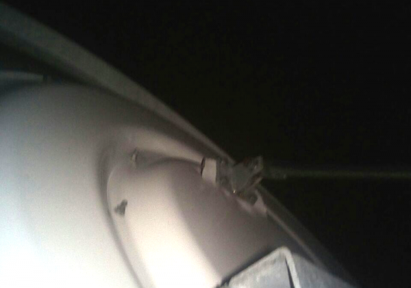
In addition to the obvious problems with power supply and connectivity with sources over IP networks, one of the main factors affecting the operability of the head station is the weather. Strong winds can easily tear or turn antennas, while wet snow sticking to the satellite dish significantly worsens reception quality. It's challenging to combat this since antennas are located as high as possible, where the weather is fierce, and even anti-icing heating of the dishes doesn't always help. Therefore, sometimes they even have to be cleaned manually.
P.S. With this, I conclude my brief excursion into the world of cable television. I hope these articles have helped broaden your horizons and discover something new in the familiar. For those who have to work with this, I recommend the book 'Cable Television Networks' by S.V. Volkova, ISBN 5-93517-190-2 for deeper understanding. It describes everything you need in an accessible manner.
Source: habr.com
