

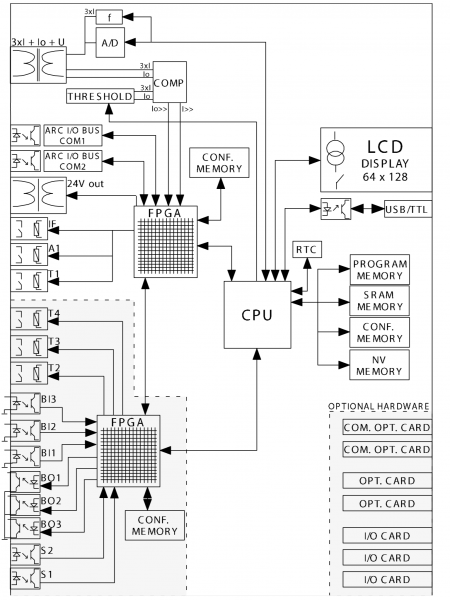
In the classical sense, arc protection in Russia is a fast-acting protection against short circuits, based on the registration of the light spectrum of an open electrical arc in switchgear. The most common method for registering the light spectrum is through fiber optic sensors, primarily used in the industrial sector. However, with the emergence of new products in the field of arc protection for residential sectors, specifically modular AFDDs that operate based on current signals, allowing for the installation of arc protection on outgoing lines, including distribution boxes, cables, connections, sockets, etc., interest in this topic is increasing.
However, manufacturers do not widely share detailed specifications of modular products (if anyone possesses such information, I would greatly appreciate links to sources), in contrast to arc protection systems for the industrial sector that come with a detailed user manual spanning 122 pages, explaining the operating principle in extensive detail.
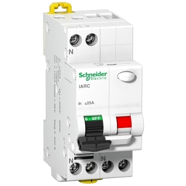
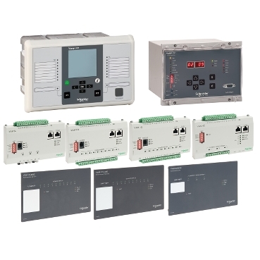
For example, let's consider the VAMP 321 arc protection system from Schneider Electric, which includes all functions for arc protection, such as overload current protection and arc presence monitoring.
Functionality
- Current monitoring across three phases.
- Zero sequence current.
- Event logs, recording of fault modes.
- Triggering can occur either simultaneously based on current and light, solely based on light, or solely based on current.
- The response time of the output with a mechanical relay is less than 7 ms, while with an optional IGBT card, the response time is reduced to 1 ms.
- Configurable triggering zones.
- Continuous self-monitoring system.
- The device can be used in various arc protection systems for low and medium voltage distribution networks.
- The arc flash detection and protection system measures the short-circuit current and signals through the arc sensor channels, and in the event of a short circuit, minimizes the burning time by quickly disconnecting the energy supply to the arc.
Matrix correlation principle
When setting activation conditions for a specific level of arc protection, logical summation is applied to the outputs of the light and current matrices.
If the protection stage is selected in only one matrix, it operates either by current condition or by light condition, thus allowing the system to be configured to work only with current signals.
Signals available for monitoring when programming protection stages:
- Phase currents.
- Zero sequence current.
- Line voltages.
- Phase voltages.
- Zero-sequence voltage.
- Frequency.
- Sum of phase currents.
- Positive sequence current.
- Negative sequence current.
- Relative value of negative sequence current.
- Ratio of negative and zero sequence currents.
- Positive sequence voltage.
- Negative sequence voltage.
- Relative value of negative sequence voltage.
- Average phase current (IL1 + IL2 + IL3) / 3.
- Average voltage UL1, UL2, UL3.
- Average voltage U12, U23, U32.
- Coefficient of nonlinear distortion IL1.
- Coefficient of nonlinear distortion IL2.
- Coefficient of nonlinear distortion IL3.
- Coefficient of nonlinear distortion Ua.
- Root mean square value IL1.
- Root mean square value IL2.
- Root mean square value IL3.
- Minimum value IL1, IL2, IL3.
- Maximum value IL1, IL2, IL3.
- Minimum value U12, U23, U32.
- Maximum value U12, U23, U32.
- Minimum value UL1, UL2, UL3.
- Maximum value UL1, UL2, UL3.
- Background value Uo.
- Root mean square value Io.
Recording of emergency modes
Recording of emergency modes can be used to save all measurement signals (currents, voltages, information about the states of digital inputs and outputs). Digital inputs also include arc protection signals.
Start recording
Recording can be initiated by triggering any protection stage or any digital input. The start signal is selected in the output signals matrix (vertical signal DR). Manual start of recording is also possible.
Self-monitoring
The device's non-volatile memory is implemented using a large-capacity capacitor and low-power RAM.
When the additional power source is on, the capacitor and RAM are powered by the internal source. When the power supply is off, the RAM starts to draw power from the capacitor. It will retain information as long as the capacitor can maintain the allowable voltage. For a room temperature of +25°C, the operating time is 7 days (high humidity reduces this parameter).
Non-volatile RAM is used for storing records of emergency modes and event logs.
The microcontroller's functions and the integrity of the associated wires, along with the correctness of the software, are monitored by a separate self-monitoring network. Besides monitoring, this network attempts to reboot the microcontroller in case of failure. If the reboot fails, the self-monitoring device sends a signal to begin indication of a permanent internal fault.
If the self-monitoring device detects a permanent fault, it blocks other output relays (except for the self-monitoring function output relay and output relays used by arc protection).
The internal power source is also monitored. In case of loss of additional power, an alarm signal is automatically generated. This means that the internal fault output relay is energized if the additional power source is on and no internal faults are detected.
The central unit, input/output devices, and sensors are monitored.
Measurements used for arc protection function
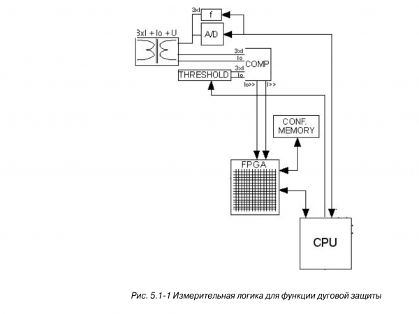
Current measurements in three phases and ground fault current for arc protection are conducted by electronics. The electronics compare the current levels with the trip setpoint values and issue binary signals “I>>” or “Io>>” for the arc protection function in case the threshold is exceeded. All current components are taken into account.
The signals “I>>” and “Io>>” are associated with the FPGA chip, which performs the arc protection function. The measurement accuracy for arc protection is ± 15% at 50Hz.
Harmonics and Total Harmonic Distortion (THD)
The device calculates THD as a percentage of the currents and voltages at the fundamental frequency.
Harmonics from 2nd to 15th are considered for phase currents and voltages. (The 17th harmonic will be partially accounted for in the 15th harmonic value due to the principles of digital measurement.)
Voltage measurement modes
Depending on the type of application and the available current transformers, the device can be connected either to zero-sequence voltage, line voltage, or phase voltage. The adjustable parameter 'Voltage Measurement Mode' must be set according to the connection used.
Available modes:
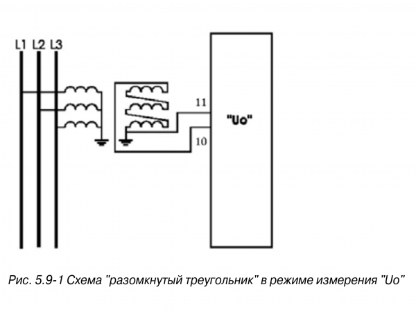
‘U0’
The device is connected to zero-sequence voltage. Directional ground fault protection is available. Measurement of line voltage, energy measurement, and voltage rise and drop protection are not available.
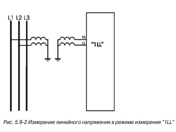
‘1LL’
The device is connected to line voltage. Measurement of voltage in one phase and rise and drop protection are available. Directional ground fault protection is not available.
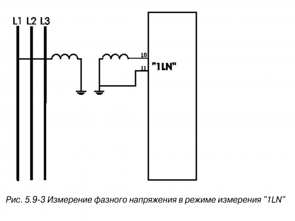
‘1LN’
The device is connected to single-phase voltage. Voltage measurement in one phase is available. In networks with solidly grounded and compensated neutrals, rise and drop protections are available. Directional ground fault protection is not available.
Symmetrical components
In a three-phase system, voltages and currents can be decomposed into symmetrical components according to Fortescue.
The symmetrical components are:
- Positive sequence.
- Negative sequence.
- Zero sequence.
Controlled objects
This device allows monitoring up to six objects, such as switches, disconnectors, or grounding blades. Monitoring can be based on a 'select-action' or 'direct control' principle.
Logical functions
The device supports user-defined software logic for signal logical expressions.
Available functions include:
- AND.
- OR.
- XOR.
- NOT.
- COUNTERs.
- RS & D flip-flops.
Source: habr.com
