


No, this is not a commercial offer; this is the cost of the system components that you can assemble after reading the article.
A bit of background:
Some time ago, I decided to keep bees, and they did appear... for a whole season, but didn't survive the winter.
This is despite the fact that I seemed to do everything correctly — autumn feeding, insulation before the cold.
The hive was a classic wooden 'Dadant' system with 10 frames made from 40mm boards.
But that winter, due to temperature 'swings', even experienced beekeepers lost far more than usual.
Thus came the idea for a hive condition monitoring system.
After publishing several articles on Habr and engaging in discussions on beekeepers' forums, I decided to start simple and move to complex solutions.
Weight is the only indisputable parameter, but existing systems usually only monitor one 'reference' hive.
If something goes wrong with it (for example, a swarm departure, bee disease), the readings become irrelevant.
Therefore, it was decided to monitor the weight changes of three hives simultaneously with one microcontroller, adding other 'features' later.
As a result, an autonomous system was created, capable of running for about a month on a single charge of a 18650 battery and sending statistics once a day.
I tried to simplify the design as much as possible so that it could be replicated even without diagrams, just using photographs.
The logic of operation is as follows: upon first startup/reset, the readings from the sensors placed under the hives are saved in EEPROM.
Then, every day after sunset, the system 'wakes up', reads the readings, and sends an SMS with the change in weight over the last 24 hours and since the moment of activation.
Additionally, the battery voltage value is transmitted, and when it drops to 3.5V, a warning is issued about the need to recharge, as below 3.4V the communication module does not activate, and the weight readings start to 'drift'.
"Do you remember how it all began? Everything was for the first time and once again."
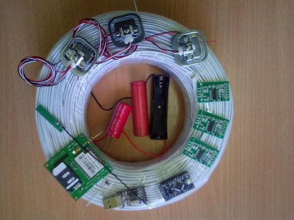
Yes, this exact hardware setup was initially planned; although only the load cells and wires survived to the final version, but that’s a story for another time.
In fact, a cable spool won't be needed; it just turned out to cost the same as 30m cut to size.
If you’re not afraid of dismantling 3 SMD LEDs and half a hundred points of regular (through-hole) soldering — then let's get started!
So, we'll need the following set of equipment/materials:
- Arduino Pro Mini 3V
Pay attention to the linear converter chip — it must be specifically 3.3V — marked with KB 33/LB 33/DE A10 — I had an issue where the entire batch from the Chinese supplier
in the store ended up with 5-volt regulators and 16MHz crystals. - USB-Ttl with a CH340 chip — a 5-volt one can be used, but then during the programming of the microcontroller, the Arduino needs to be disconnected from the GSM module to avoid burning it out.
Boards with a PL2303 chip do not work under Windows 10. - GSM communication module Goouu Tech IOT GA-6-B or AI-THINKER A-6 Mini.
Why did I settle on it? Neoway M590 is a builder that requires some tricky handling, while GSM SIM800L's non-standard 2.8V logic level requires matching even with a three-volt Arduino.
Moreover, the solution from AiThinker has minimal power consumption (when sending SMS, I haven't seen current above 100mA). - GSM GPRS 3DBI antenna (shown in the photo above — a rectangular board with a 'tail' at 9 o'clock)
- Starter kit from an operator with good coverage in the location of your apiary.
Yes, the package needs to be activated in a regular phone beforehand, DISABLE PIN REQUEST upon entry, and recharge.
Now there are many options with names in the style of 'Sensor', 'IoT' — they have slightly lower subscription fees. - Dupont wire 20cm female-female — 3 pcs. (for connecting Arduino to USB-TTL)
- 3 pcs. HX711 — ADC for scales
- 6 load cells for weights up to 50kg
- 15 meters of 4-wire telephone cable — for connecting weight modules to Arduino.
- GL5528 photoresistor (it is important to have exactly this one, with a dark resistance of 1MΩ and a light resistance of 10-20kΩ) and two regular 20kΩ resistors.
- A piece of double-sided 'thick' tape 18x18mm — for attaching the Arduino to the communication module.
- A 18650 battery holder and, actually, the battery itself ~2600mAh.
- A bit of wax or paraffin (an aroma lamp tablet candle) — for moisture protection of the HX711.
- A piece of wood beam 25x50x300mm for the base of the load cells.
- A dozen self-tapping screws with press washers 4.2x19 mm for securing the sensors to the base.
The battery can be taken from disassembled laptops — it's significantly cheaper than new, and the capacity will be greater than a Chinese UltraFire — I ended up with 1500 compared to 450 (the fire has 6800 😉
In addition, you will need steady hands, an EPSN-25 soldering iron, rosin, and POS-60 solder.
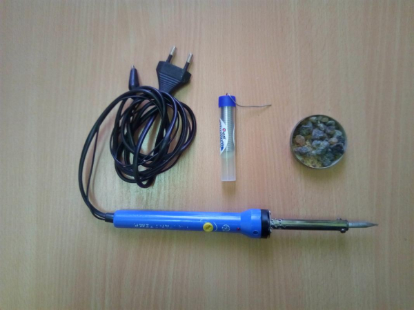
Five years ago, I was using a Soviet soldering iron with a copper tip (soldering stations never appealed to me — I borrowed one for a test drive, and ended up using an EPSN).
But after it broke down and several monstrous Chinese knock-offs, the last one named Sparta—was as tough as its name, I stopped
on the product with a temperature controller.
So, let's get started!
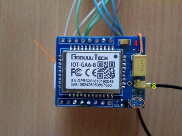
First, we desolder two LEDs from the GSM module (the spot where they were is outlined in an orange oval)
Insert the SIM card with the contact pads facing the circuit board; the cut corner in the photo is marked with an arrow.
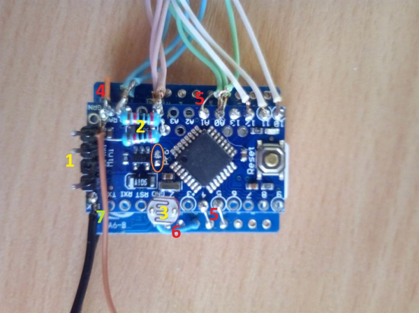
Next, we perform the same procedure with the LED on the Arduino board (the oval is to the left of the square chip),
We solder a header with four contacts (1),
We take two 20k resistors, twist the leads together on one end, solder the twist into the A5 contact hole, and connect the remaining leads to RAW and GND of the Arduino (2),
We shorten the legs of the photoresistor to 10mm and solder it to the GND and D2 pins of the board (3).
Now it's time for the blue double-sided tape — we stick it on the SIM card holder of the communication module, and on top — the Arduino — the red (silver) button is facing us and is above the SIM card.
We solder the power supply: the positive from the capacitor of the communication module (4) to the RAW contact of the Arduino.
The thing is, the module itself requires a power supply of 3.4-4.2V, and its PWR contact goes to a step-down converter, so to operate from a li-ion battery, the voltage must be supplied bypassing this part of the circuit.
In Arduino, on the other hand, we supply power through a linear converter — at low current consumption, the drop-out voltage is 0.1V.
However, by supplying stabilized voltage to the HX711 modules, we eliminate the need to modify them for lower voltage (and at the same time, we avoid increased noise as a result of this operation).
Next, we solder jumpers (5) between the PWR-A1, URX-D4, and UTX-D5 contacts, 'ground' GND-G (6), and finally, power from the 18650 battery holder (7), and connect the antenna (8).
Now we take a USB-TTL converter and connect it with Dupont wires to the ARDUINO (header 1) RXD-TXD and TXD-RXD contacts, GND-GND:
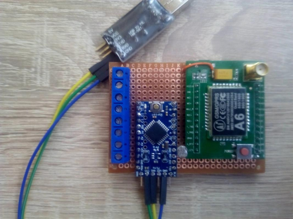
In the photo above is the first version (of three) of the system that was used for debugging.
And now we will take a break from the soldering iron for a while and move on to the software part.
I will describe the sequence of actions for Windows:
First, you need to download and install/unpack the program. — the current version is 1.8.9, but I am using 1.6.4.
For convenience, unpack the archive into the folder C:arduino-«your_version_number», inside which we will have folders /dist, drivers, examples, hardware, java, lib, libraries, reference, tools, as well as the executable file arduino (among others).
Now we will need a library to work with the ADC. — the green button "clone or download" — download ZIP.
The contents (folder HX711-master) go into the directory C:arduino-«your_version_number»libraries.
And of course, a driver for from the same github — simply run the installer from the unpacked archive using the SETUP file.
Okay, let's launch and configure the program C:arduino-«your_version_number»arduino.
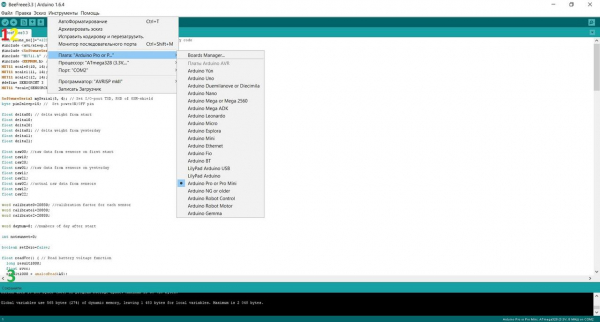
Go to the "Tools" section - select the board "Arduino Pro or Pro Mini", processor Atmega 328 3.3V 8 MHz, port — a number other than system COM1 (it appears after installing the CH340 driver with the USB-TTL adapter connected).
Alright, copy the following sketch (program), and paste it into the Arduino IDE window.
char phone_no[]="+123456789012"; // Your phone number that receive SMS with counry code
#include <avr/sleep.h>  // ARDUINO sleep mode library
#include <SoftwareSerial.h> // Sofrware serial library
#include "HX711.h" // HX711 lib. https://github.com/bogde/HX711
#include <EEPROM.h> // EEPROM lib.
HX711 scale0(10, 14);
HX711 scale1(11, 14);
HX711 scale2(12, 14);
#define SENSORCNT 3
HX711 *scale[SENSORCNT];

SoftwareSerial mySerial(5, 4); // Set I/O-port TXD, RXD of GSM-shield
byte pin2sleep=15; //  Set powerON/OFF pin

float delta00; // delta weight from start
float delta10;
float delta20;
float delta01; // delta weight from yesterday
float delta11;
float delta21;

float raw00; //raw data from sensors on first start
float raw10;
float raw20;
float raw01; //raw data from sensors on yesterday
float raw11;
float raw21;
float raw02; //actual raw data from sensors
float raw12;
float raw22;

word calibrate0=20880; //calibration factor for each sensor
word calibrate1=20880;
word calibrate2=20880;

word daynum=0; //numbers of day after start

int notsunset=0;

boolean setZero=false;

float readVcc() { // Read battery voltage function
  long result1000;
  float rvcc;
  result1000 = analogRead(A5);
  rvcc=result1000;
  rvcc=6.6*rvcc/1023;
  return rvcc;
}

void setup() { // Setup part run once, at start

  pinMode(13, OUTPUT);  // Led pin init
  pinMode(2, INPUT_PULLUP); // Set pullup voltage
  Serial.begin(9600);
  mySerial.begin(115200); // Open Software Serial port to work with GSM-shield
  pinMode(pin2sleep, OUTPUT);// Itit ON/OFF pin for GSM
  digitalWrite(pin2sleep, LOW); // Turn ON modem
  delay(16000); // Wait for its boot

scale[0] = &scale0; //init scale
scale[1] = &scale1;
scale[2] = &scale2;

scale0.set_scale();
scale1.set_scale();
scale2.set_scale();

delay(200);

setZero=digitalRead(2);

if (EEPROM.read(500)==EEPROM.read(501) || setZero) // first boot/reset with hiding photoresistor
//if (setZero)
{
raw00=scale0.get_units(16); //read data from scales
raw10=scale1.get_units(16);
raw20=scale2.get_units(16);
EEPROM.put(500, raw00); //write data to eeprom
EEPROM.put(504, raw10);
EEPROM.put(508, raw20);
for (int i = 0; i <= 24; i++) { //blinking LED13 on reset/first boot
    digitalWrite(13, HIGH);
    delay(500);
    digitalWrite(13, LOW);
    delay(500);
  }
}
else {
EEPROM.get(500, raw00); // read data from eeprom after battery change
EEPROM.get(504, raw10);
EEPROM.get(508, raw20);
digitalWrite(13, HIGH); // turn on LED 13 on 12sec.
    delay(12000);
digitalWrite(13, LOW);
}

delay(200); // Test SMS at initial boot

//
  mySerial.println("AT+CMGF=1");    //  Send SMS part
  delay(2000);
  mySerial.print("AT+CMGS="");
  mySerial.print(phone_no);
  mySerial.write(0x22);
  mySerial.write(0x0D);  // hex equivalent of Carraige return
  mySerial.write(0x0A);  // hex equivalent of newline
  delay(2000);
  mySerial.println("INITIAL BOOT OK");
  mySerial.print("V Bat= ");
  mySerial.println(readVcc());
 if (readVcc()<3.5) {mySerial.print("!!! CHARGE BATTERY !!!");}
  delay(500);
  mySerial.println (char(26));//the ASCII code of the ctrl+z is 26
  delay(3000);

//

raw02=raw00;
raw12=raw10;
raw22=raw20;

//scale0.power_down(); //power down all scales
//scale1.power_down();
//scale2.power_down();

}

void loop() {

  attachInterrupt(0, NULL , RISING); // Interrupt on high lewel
  set_sleep_mode(SLEEP_MODE_PWR_DOWN); //Set ARDUINO sleep mode
  digitalWrite(pin2sleep, HIGH); // Turn OFF GSM-shield
  delay(2200);
  digitalWrite(pin2sleep, LOW); // Turn OFF GSM-shield
  delay(2200);
  digitalWrite(pin2sleep, HIGH);
  digitalWrite(13, LOW);
  scale0.power_down(); //power down all scales
  scale1.power_down();
  scale2.power_down();
  delay(90000);
  sleep_mode(); // Go to sleep
  detachInterrupt(digitalPinToInterrupt(0)); // turn off external interrupt

  notsunset=0;
 for (int i=0; i <= 250; i++){
      if ( !digitalRead(2) ){ notsunset++; } //is a really sunset now? you shure?
      delay(360);
   }
  if ( notsunset==0 )
  {
  digitalWrite(13, HIGH);
  digitalWrite(pin2sleep, LOW); // Turn-ON GSM-shield
  scale0.power_up(); //power up all scales
  scale1.power_up();
  scale2.power_up();
  raw01=raw02;
  raw11=raw12;
  raw21=raw22;
  raw02=scale0.get_units(16); //read data from scales
  raw12=scale1.get_units(16);
  raw22=scale2.get_units(16);

  daynum++;
  delta00=(raw02-raw00)/calibrate0; // calculate weight changes
  delta01=(raw02-raw01)/calibrate0;
  delta10=(raw12-raw10)/calibrate1;
  delta11=(raw12-raw11)/calibrate1;
  delta20=(raw22-raw20)/calibrate2;
  delta21=(raw22-raw21)/calibrate2;

  delay(16000);
  mySerial.println("AT+CMGF=1");    //  Send SMS part
  delay(2000);
  mySerial.print("AT+CMGS="");
  mySerial.print(phone_no);
  mySerial.write(0x22);
  mySerial.write(0x0D);  // hex equivalent of Carraige return
  mySerial.write(0x0A);  // hex equivalent of newline
  delay(2000);
  mySerial.print("Turn ");
  mySerial.println(daynum);
  mySerial.print("Hive1  ");
  mySerial.print(delta01);
  mySerial.print("   ");
  mySerial.println(delta00);
  mySerial.print("Hive2  ");
  mySerial.print(delta11);
  mySerial.print("   ");
  mySerial.println(delta10);
  mySerial.print("Hive3 ");
  mySerial.print(delta21);
  mySerial.print("   ");
  mySerial.println(delta20);

  mySerial.print("V Bat= ");
  mySerial.println(readVcc());
  if (readVcc()<3.5) {mySerial.print("!!! CHARGE BATTERY !!!");}
  delay(500);
  mySerial.println (char(26));//the ASCII code of the ctrl+z is 26
  delay(3000);

  }

}
In the first line, in quotes char phone_no[]="+123456789012"; — instead of 123456789012, put your phone number with the country code, to which the SMS will arrive.
Now click the check button (above the number one in the screenshot above) — if at the bottom (under the three on the screen) it says "Compilation completed" — then we can flash the microcontroller.
So, USB-TTL is connected to the ARDUINO and the computer; place the charged battery in the holder (usually on a new Arduino, the LED starts blinking at a frequency of once per second).
Now for the flashing — practice pressing the red (silver) button on the microcontroller — this needs to be done at a specific moment!!!
Got it? Click the "Upload" button (above the number two in the screenshot), and watch carefully the line at the bottom of the interface (under the three on the screen).
As soon as the text "compilation" changes to "uploading" — press the red button (reset) — if everything is okay — the lights on the USB-TTL adapter will joyfully blink, and at the bottom of the interface, it will say "Uploaded".
Now while we wait for the test SMS to arrive on the phone, let me explain how the program works:
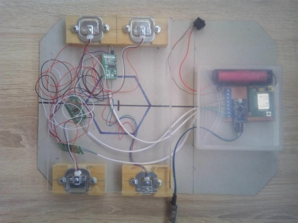
In the photo — the second version of the test bench.
When powered on for the first time, the system checks bytes number 500 and 501 in the EEPROM; if they are equal, then the calibration data is not recorded, and the algorithm proceeds to the setup section.
The same thing happens if the photoresistor is covered (with a pen cap) when turned on — the parameter reset mode is activated.
The load cells should already be installed under the hives, as we just fix the initial zero level and then measure the weight change (currently just zeros will come since we haven't connected anything yet).
The built-in LED on pin 13 will start blinking on the Arduino.
If the reset does not occur, the LED lights up for 12 seconds.
After that, a test SMS is sent with the message 'INITIAL BOOT OK' and the battery voltage.
The communication module turns off, and after 3 minutes, the Arduino board puts the HX711 ADC boards into sleep mode and itself goes to sleep.
This delay is made to avoid picking up noise from the operating GSM module (after turning off, it 'backgrounds' for a while).
Next, we have an interrupt by the photodetector on the second pin (the pull-up is enabled).
After triggering, the state of the photoresistor is checked for another 3 minutes — to exclude false triggers.
Interestingly, without any adjustment, the system triggers 10 minutes after astronomical sunset in overcast weather and 20 minutes in clear weather.
Yes, to ensure that the system does not reset on each activation, at least the first HX711 module must be connected (pins DT-D10, SCK-A0).
Then the readings from the load cells are taken, the weight change from the previous trigger (the first number in the line after Hive) and from the first activation is calculated, the battery voltage is checked, and this information is sent as an SMS:
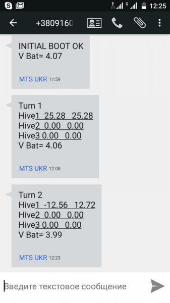
By the way, did we receive the SMS? Congratulations! We are halfway there! The battery can now be removed from the holder, we won’t need the computer further.
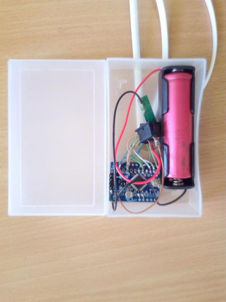
By the way, the flight control center turned out so compact that it can fit into a mayonnaise jar; in my case, a translucent box measuring 30x60x100mm (from business cards) worked perfectly.
Yes, the sleeping system consumes about 2.3mA — 90% due to the communication module — it does not turn off completely but goes into standby mode.
Let’s start making the sensors; first, let's touch on the layout of the sensors:
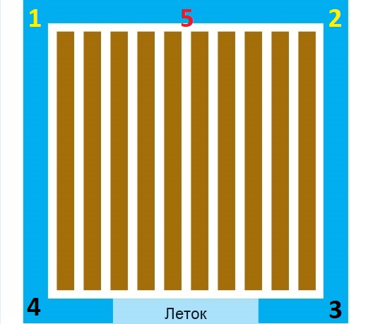
This is a plan of the hive — top view.
Classically, 4 sensors are installed at the corners (1,2,3,4).
We will measure differently. More precisely, even in a third way. Since the guys from BroodMinder do it differently:
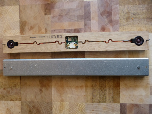
In this design, the sensors are installed at positions 1 and 2, while points 3 and 4 rely on the beam.
Then, only half the weight is placed on the sensors.
Yes, this method has lower accuracy, but it's hard to imagine bees filling all frames with 'tongues' of honeycombs along one wall of the hive.
So, I suggest consolidating the sensors at point 5 — this eliminates the need for shielding the system, and with lightweight hives, we can manage with just one sensor.
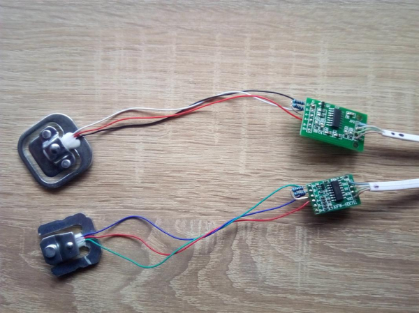
In total, two types of modules were tested on the HX711, two types of sensors, and two connection options — with a full Wheatstone bridge (2 sensors) and a half bridge, where the second part is supplemented with 1k ohm resistors with a tolerance of 0.1%.
However, the last method is undesirable and not recommended even by the sensor manufacturers, so I will describe only the first one.
Thus, we will install two strain gauges and one HX711 module for one hive; the wiring scheme is as follows:
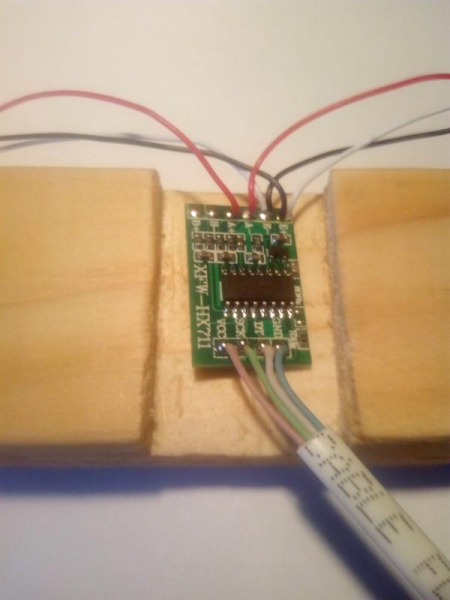
Five meters of 4-wire telephone cable goes from the ADC board to the Arduino — .
In general, we leave 8 cm 'tails' on the sensors, strip the twisted pair, and connect everything as shown in the photo above.
Before starting the woodworking part, place wax/paraffin in a suitable container to melt in a water bath.
Now take our beam and divide it into three segments of 100 mm each.
Next, we mark a longitudinal groove 25 mm wide and 7-8 mm deep, and using a saw and chisel, remove the excess — it should come out as a U-shaped profile.
Is the wax melted? — Dip our ADC boards in there — this will protect them from moisture/fog:
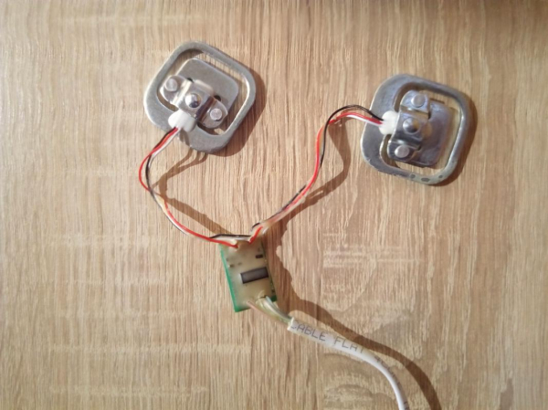
We place all this on a wooden base (it needs to be treated with an antiseptic against rot):
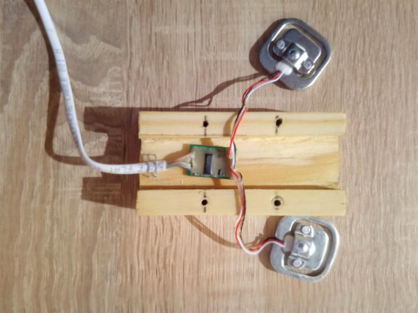
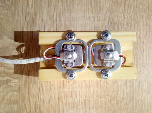
And finally, we fix the sensors with self-tapping screws:
There was also an option with blue tape, but for humanitarian reasons, I won't mention it 😉
From the Arduino side, we do the following:
We strip our telephone cables, twist the colored wires together, and tin them.
After that, we solder to the contacts of the board as shown in the photo:
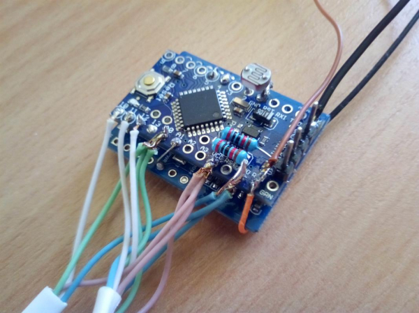
That's it, now for the final check, we place the sensors in sectors of the circle, on top — a piece of plywood, we reset the controller (install a battery with the cap from a pen covering the photodiode).
The LED on the Arduino should blink, and a test SMS should arrive.
Next, remove the cap from the photoresistor and go fill a 1.5-liter plastic bottle with water.
Place the bottle on the plywood, and if a few minutes have passed since switching on, put the cap back on the photoresistor (simulating sunset).
After three minutes, the LED on the Arduino will light up, and you should receive an SMS with weight values around 1 kg in all positions.
Congratulations! The system has been successfully assembled!
If you now trigger the system again, the weight in the first column will show zeros.
Yes, in real conditions, the photoresistor should ideally be oriented vertically upwards.
Now I will provide a brief manual on usage:
- Install the load cells under the back walls of the hives (put a beam/board about 30mm thick under the front).
- Shade the photoresistor and connect the battery— the LED should blink, and a test SMS with the text 'INITIAL BOOT OK' should arrive.
- Position the central unit as far from the hives as possible, ensuring that the wires do not obstruct when working with bees.
Every evening, after sunset, an SMS will be sent with the weight changes over the day and since the launch.
When the battery voltage reaches 3.5V, the SMS will end with the line '!!! CHARGE BATTERY !!!'.
The operating time on a single 2600mAh battery is about a month.
In case of battery replacement, daily weight changes of the hives are not recorded.
UPD WARNING!
UNDER CONDITIONS OF WEAK SIGNAL, the GSM module increases power, leading to SYSTEM REBOOT.
This was discovered during 'field' tests (it is unclear why users of GSM shields do not report such issues).
I am currently preparing a new scheme:
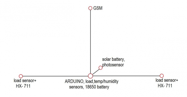
After successful testing, this publication will be updated.
Electro-beekeeper Andrey.
Source: habr.com
