

The release of the free package for PCB design automation, LibrePCB 2.0.0, has been announced. LibrePCB is positioned as an intuitive package for rapid board development, which lags behind KiCad in functionality but is much easier to work with, catering to the needs of both beginners and professional engineers. The program is available in builds for Linux (Flatpak, Snap, AppImage), FreeBSD, macOS, and Windows. The project code is written in C++ and is distributed under the GPLv3 license.
Notable features include the integration of a schematic editor and project management tools in one package; a simple cross-platform graphical interface based on Qt; the use of a "smart" library concept; the ability to utilize accessible formats for manual parsing of component libraries and projects; a Multi-PCB mode for parallel development of different board variants based on a single schematic; and automatic synchronization of the netlist between the schematic and the board layout. The program is equipped with a multilingual interface supporting Russian (translation coverage 82%) and Ukrainian languages (translation coverage 72%), allowing for component names in different languages.
LibrePCB includes a project management interface; an electronic schematic editor; a multilayer PCB editor; a service for generating data to start production; a command-line utility, librepcb-cli, for automating routine tasks (such as checking and exporting data); and a library of electronic components with navigation via a tree-structured categorized list. It has an interface for connecting various existing component libraries, which can be added as archives or through integration with repositories. Importing DXF files and exporting in PDF, SVG, and CSV BOM formats, pick & place X3/CSV, Gerber/Excellon, and STEP is supported.
Key innovations:
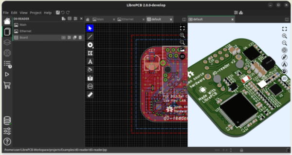
- The new user interface has been introduced, redesigned from the ground up using the Slint framework, written in Rust (the LibrePCB code remains in C++, with a C++ wrapper applied over Slint for the interface). The new interface notably replaces five separate specialized windows with a single unified window. Simultaneous work with different projects and libraries is implemented through tabs that can be placed side by side, for example, for viewing different schematics, 3D models, and 2D images of the board simultaneously, or for viewing multiple schematics at once. In multi-monitor configurations, it is possible to have different windows with their own set of tabs on each monitor.

- The library manager and editor have been redesigned as tabs that open in the main window. The sidebar provides notifications about outdated libraries.
- The ordering function for PCB production has been rewritten and transformed into a tab, which now automatically carries out ERC (Electrical Rule Check) and DRC (Design Rule Check) checks, helping to avoid issues due to forgotten checks before placing an order.
- The interface capabilities for 3D board visualization have been expanded. Support for hiding individual objects and layers has been added to simplify the inspection of details.
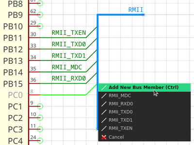
- The capability for working with buses in schematics has been implemented, allowing multiple tracks to be grouped into a single thick line for improved readability of the schematics.

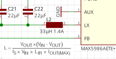
- The ability to add labels to the schematic formatted as SVG, PNG, and JPEG images has been introduced, which can be useful for including diagrams, formulas, tables, or logos in the schematic.

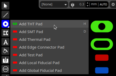
- The option for arbitrary placement of pads (THT or SMT) or plated holes has been added, without binding them to components.

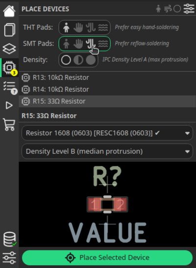
- The option to specify a preferred soldering method has been provided, for example, users can specify manual soldering or reflow soldering and LibrePCB will automatically generate the necessary footprints.

Source: opennet.ru
