

In the first five steps described in the article we created a virtual network connecting three geographically distant nodes. One of them is located in a physical network, while the other two are in two separate data centers.
It didn't take much time, although each of these nodes was added to the network one by one. But what if we need to connect not just one, but all the nodes in the physical network to the ZeroTier virtual network? This challenge once arose when I was trying to set up access from the virtual network to a network printer and router.
I tried using the method described above — it wasn't quick and wasn't straightforward everywhere. For example, a network printer cannot be connected just like that. Mikrotik — ZeroTier is not supported. What to do? After much searching and analyzing the networking topic, I concluded that I needed to set up a network bridge.
Network bridge (also bridge from English) — a Layer 2 network device in the OSI model, designed to connect segments (subnets) of a computer network into a unified network.
I want to share my story of how I did this in this article.
What does it take to build a bridge...
First, as the administrator, I needed to determine which node in the network would function as the bridge. After studying the options, I realized that it could be any computer device that has the capability to create a bridge between network interfaces. It could be a router — a device or , or even a regular server or computer.
Initially, I of course considered using a router with OpenWRT. But given that the existing Mikrotik satisfies me completely, even though it doesn't support integration with ZeroTier, I really don't want to complicate things, so I decided to use a computer as the network bridge. Specifically, a Raspberry Pi 3 Model B that is constantly connected to the physical network and running the latest version of Raspbian — an OS based on Debian Buster.
To set up a bridge, one unused network interface must be available on the device, which is not used by other services. In my case, the main Ethernet was already in use, so I organized a second one. I used a USB-Ethernet adapter based on the RTL8152 chipset from Realtek for this task.
After connecting the adapter to a free USB port, updating, and rebooting the system:
sudo apt update && sudo apt upgrade -y
sudo reboot
I checked if the system recognized the USB Ethernet adapter:
sudo lsusbAnalyzing the received data
Bus 001 Device 004: ID 0bda:8152 Realtek Semiconductor Corp. RTL8152 Fast Ethernet Adapter
Bus 001 Device 003: ID 0424:ec00 Standard Microsystems Corp. SMSC9512/9514 Fast Ethernet Adapter
Bus 001 Device 002: ID 0424:9514 Standard Microsystems Corp. SMC9514 Hub
Bus 001 Device 001: ID 1d6b:0002 Linux Foundation 2.0 root hub
I noted with satisfaction that Device 004 was indeed my adapter.
Next, I clarified which network interface was assigned to this adapter:
dmesg | grep 8152[ 2.400424] usb 1-1.3: New USB device found, idVendor=0bda, idProduct=8152, bcdDevice=20.00
[ 6.363837] usbcore: registered new interface driver r8152
[ 6.669986] r8152 1-1.3:1.0 eth1: v1.09.9
[ 8.808282] r8152 1-1.3:1.0 eth1: carrier onIt turned out eth1 🙂 And I can already configure it and the network bridge.
Which is exactly what I did by following the algorithm below:
- I installed the packages to manage the network bridge:
sudo apt-get install bridge-utils - ZeroTier ONE:
curl -s https://install.zerotier.com | sudo bash - it to the existing ZeroTier network:
sudo zerotier-cli join - I executed the command to disable ZeroTier IP address and routing management:
sudo zerotier-cli set allowManaged=0
Next, on my network controller:
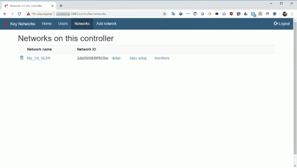
In Networks I clicked on detail, found and followed the link v4AssignMode and disabled auto-assignment of IP addresses by unchecking the checkbox Auto-assign from IP Assignment Pool
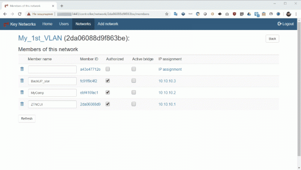
After that, I authorized the connecting node by assigning a name and checking the boxes Authorized and Active Bridge. I did not assign an IP address.
Then I returned to configuring the network bridge on the node, for which I opened the network interfaces configuration file for editing via the terminal:
sudo nano /etc/network/interfacesWhere I added the following lines
auto eth1
allow-hotplug eth1
iface eth1 inet manual

auto br0
allow-hotplug br0
iface br0 inet static
        address 192.168.0.10
        netmask 255.255.255.0
        gateway 192.168.0.1
        network 192.168.0.0
        broadcast 192.168.0.255
        dns-nameservers 127.0.0.1
        bridge_ports eth1 ztXXXXXXXX
        bridge_fd 0
        bridge_maxage 0
Where eth1 — the connected USB Ethernet adapter, to which I did not assign an IP address.
br0 — Creating a network bridge with a designated static IP address from the range of addresses in my physical network.
ztXXXXXXXX — the name of the ZeroTier virtual interface I obtained using the command:
sudo ifconfigAfter entering the information, I saved the configuration file and restarted the network services with the command:
sudo /etc/init.d/networking restartTo check the functionality of the bridge, I executed the command:
sudo brctl show According to the received data, the bridge is up.
bridge name	bridge id		STP enabled	interfaces
br0		8000.00e04c360769	no		eth1
							ztXXXXXXXX
Next, I went to the network controller to set the route.
For this, I clicked on the link in the list of network nodes IP assignment of the network bridge. Then, in the opened window, I clicked on Managed routes. I moved to a new page where as Target indicated 0.0.0.0/0, and as Gateway — the IP address of the network bridge from the range of addresses specified earlier for the organization. In my case, 192.168.0.10.
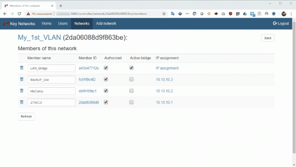
I confirmed the entered data and started checking the network connectivity of the nodes, pinging from the physical network node to the virtual network node and vice versa.
And that’s it!
In my case, however, unlike the prototype from which the screenshots were taken, the IP addresses of the virtual network nodes are from the same range as those of the physical network nodes. With bridged connection of networks, this model is possible, provided they do not overlap with the addresses assigned by the DHCP server.
I won’t discuss configuring the network bridge on the MS Windows node and other Linux distributions in this article — there is plenty of material on this subject available online. As for the configuration on the side of the network controller — it is identical to the one described above.
I just want to point out that Raspberry PI is a budget-friendly and convenient tool for connecting networks with ZeroTier, not only as a stationary solution. For example, outsourcers can utilize a pre-configured network bridge based on Raspberry PI for quickly linking the physical network of a client being serviced with virtual ones based on ZeroTier.
I will now conclude this part of the narrative. I welcome questions, feedback, and comments — as it is based on them that I will build the content of the next article. For now, I invite you to try to set up your own virtual network using a private network controller with a GUI based on a VDS from the marketplace. RUVDS. Moreover, all new clients benefit from a free trial period of 3 days!
->
->
->
Source: habr.com
