

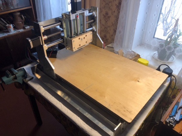
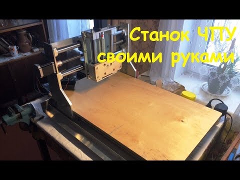
I am assembling another portal milling machine with a small working field, for wood, plastic, composites. This story is given under the cut ...
I will say right away - not everyone has what I have lying around in the garage. In view of some third-party mechanical projects, I have accumulated some rubbish, which later could simply rust, after which, it was only ferrous metal. I attributed polished guide shafts to this type of rubbish, a few scraps of duralumin sheets (although they do not rust, they take up space). I also had a stepper motor and driver available.
Among other things, from the main one, it remains to complete my existing set: ball screws, carriages for guide shafts, motors, electronics and a spindle. In general, "very little". And in the presence of all this, apart from all sorts of little things in the form of metalworking and various hardware, I will get a CNC machine.
Having estimated the price tag for the missing components, and realizing that I could handle such an amount without much financial difficulty (especially if I didn’t buy everything at once, but as I assembled), I nevertheless decided to take such a rash step and started designing the future machine.
Based on the lengths of the guides and the dimensions of the duralumin trimmings (fortunately, they were all about the same size), I started by drawing the base.
Dimensions:
Trimmings - length 700mm, height 70mm, thickness 6mm.
Guides (4 pieces) - diameter 25mm, length 740mm.
From these dimensions, and repelled during the construction of the entire structure. Accordingly, the length of the portal movement along the base turned out to be 600mm (X coordinate).
Due to the fact that there are only 4 guides, and it was not planned to buy them in addition, and besides, the machine has three axes of movement, I had to divide two guides into two smaller axes: Y and Z. I divided it so that the width of the working field along Y turned out to be 250mm , and in Z - 80mm.
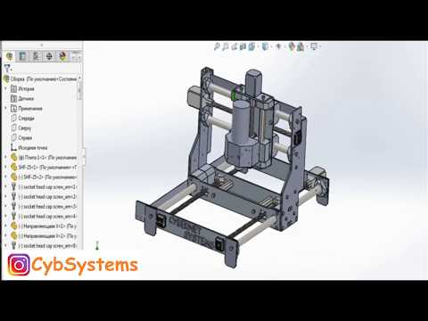
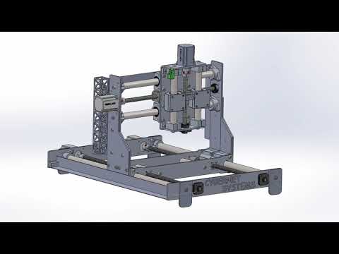
Since this is not my first CNC machine project, instead of the usual KOMPAS 3D, I used SolidWorks. It redrawn all the standard parts I had and ordered (motors, couplings, carriage guides, bearing supports, ball screws, guide supports) that did not require additional processing. Then he began to add guides to the project, began to connect them with duralumin sheets, in which he made technological holes for mounting and installing engines, and reinforcing supports.
Speaking of the latter. To save money, the supports for the guides could not be installed, but since the thickness of the sheet is too small in my opinion, I considered that such supports would significantly strengthen the structure.
It was decided to move the portal itself by installing two ball screws along the edges, and not one in the center, although this is a little more expensive, but there is no need to worry about the weight of the portal.
After the base was ready, I started drawing the portal. I drew the main beam, which will carry the portal and move it along the entire base. The beam turned out to be quite strong due to parallel plates fastened and pulled together by cylindrical axes. The main plane of attachment to the carriages was matched with the plates forming the portal racks. They were reinforced with a 6mm thick sheet (I also had it in the garage). Everything else was painted in the same way as the base.
Having attached the guide carriages and the ball screw nut along the Y axis to the project, I threw on the mechanism for moving the Z axis. It already used T-shaped guide supports, and an end plate is attached to the guide carriages, which mates with the spindle.
I want to make a small digression and tell you about the use of cylindrical guides by me. I know that some “experts” in the comments will say that these guides will sag, the accuracy will be poor, the rigidity of the structure is also no and stuff like that. For processing those materials on which this machine is made and when using such a diameter of the guides, for such a length as mine, the deflection will be negligible, the rigidity is more than enough.
In the whole design, I used a ball screw with a diameter of 16mm with a step of 5mm.
After outlining the power frame of the machine, I added several auxiliary elements to it, such as corners on which a flexible cable channel should lie and supports attached to the base of the machine.
The production of parts for the machine began in the same sequence in which he painted them. I processed parts from scraps and a sheet of duralumin on my last project - a CNC machine. I will say right away, if you count in the total population, then it took no more than 8 hours to process all the flat parts. I spent more time choosing the cutting mode and waiting for a few cutters I needed.
I mainly used a single-bladed cutter with a diameter of 6mm, and also for small holes a double-bladed cutter with a diameter of 3mm. Of course, there were some broken cutters, but in the end it's an experience, although not as cheap as we would like.
The guides and tails of the ball screws were sharpened by my friends, there were also jambs. These are all trifles, this happens when a person has been drinking heavily all his life, and then abruptly quit.
The machine was assembled as a constructor, it seems that at one time I did not play enough with them and now I make up for this by assembling and designing machines. It's nice when all the details fit together and almost do not need to modify and customize them. However, it still needed to be improved. There was a difficulty with the pairing of motors and ball screws.
By ordering an additional three motors similar to the one I already had, as well as 4 couplings for connecting the motor shafts and ball screws. When everything ordered arrived, it turned out that the diameter of the output shafts of the engines was 6,2 mm, and the couplings that arrived were with holes of 8 and 12 mm, which is what you need, since the output shaft I had in my presence was 8 mm. In the end, I ordered three new couplings with a diameter of 6 and 12mm, after which I simply reamed the hole to 6,2mm.
It remains unclear why the motor shaft is 0,2 mm larger and what kind of standards they have in general, or does it all depend on the specific manufacturer, what kind of rod was available as a shaft and did you decide to use it?
Be careful when ordering.
The mechanical part is almost ready, now you can move on to the electrical part. Motors connected to drivers. Two X-axis motors, connected in parallel to one DM542 driver, connected the others to cheaper drivers (no name) based on TB6600. I connected all three drivers to the DDCSV2.1 controller on 4 axes, only the fourth axis, namely the rotary one, cannot be assigned as duplicating any of the main three. Together with the controller, the MPG remote control for manual control of the coordinates was included - a cool thing. I think in the future she will not stop liking me and will continue to please me.
At the moment, I made a hinged installation and did not stretch normal wires, and not all parts have been bought yet. In fact, I connected it to check the functionality of the mechanics. The other day I just ordered a 1,5 kW air-cooled spindle. and a frequency converter with collets.
In the future, I will install the spindle, and I will breed the wires; I will make and assemble a box for electronics.
In the final part, I will show and tell you what kind of animal I got, let's talk about its pros and cons and draw conclusions.
Thank you for your attention and happy reading!
Source: habr.com
